|
St Francis |
|

Engine, Saildrive, and Fuel System Upgrades
Last Updated: 01/25/2026
Propeller Choices
We had a fixed prop on our CSY 44 Monohull, and I was convinced that was the correct choice at the time. You can read my thoughts from 2008 about fixed vs folding vs feathering props here.
Our catamaran came with a pair of two-bladed aluminum props. But there was no spare prop included, and the originals looked pretty worn out. We really needed a new pair of props.
There are quite a few feathering/folding props to choose from. There's no question that a feathering prop is the best choice for pure sailing. I believe they will give you almost 3/4 knot speed boost, not having to drag that big prop while sailing. The down side is the huge difference in cost.
|
The Original St. Francis 44 Prop |
|
 |
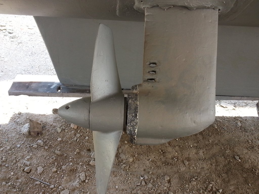 |
A friend was enthusiastic about Kiwi Props, made out of a lightweight composite material. So instead of buying a spare aluminum prop, I bought a pair of Kiwi Props. They cost $1500 USD each, delivered to Florida, and come with spare blades.
 |
|
 |
|
 |
I do believe they have increased our speed under sail. But the composite blades are not bulletproof. We have already broken one blade by running into a heavy semi-submerged piece of wood. However, it was an easy matter to fit a new spare blade, which we did by just pulling into a shallow sandy spot and doing the replacement in the water.
After the first year of use, in which we had no problems, we had a little trouble this year going into reverse. We carefully inspected the props several times for growth, but could not find anything externally on the props that would cause a problem.
Now that the boat is hauled out for maintenance, we have not taken the time to try to track down what the problem is--a transmission issue or a propeller issue.
Back to topComing Soon: Saildrive Gear Oil Header Tanks
See Ocelot's Saildrive Header Tank solution here.
After having suffered through leaking seals at the prop shaft due to excessive corrosion we finally opted to buy and install new saildrive SD20 legs for our 3GM30 Yanmar engines.
At the same time we replaced most of the seals and o-rings from the engine rear main seal through the rest of the saildrive machinery, since we had the entire drive train apart inside the boat. In doing this we discovered that two strong workers and an 8' pole were the best way to get the small Yanmar engines, once disconnected, off their mounts and oriented for easy work access.
Pulling the leg up with the gear box attached from inside the hull is very difficult, involving taking the engine off its mounts and removing the adapter plate and a diaphragm. But since we had other leak issues along the drive train we did it that way initially.
Removing and Replacing Saildrive Legs from the Outside
The sail drive legs will also come off from the water side with a bit of enlargement of the outer leg access holes. Should you need to remove and replace the saildrive legs, here are some things I have learned after removing mine 4 times for various reasons:
-
Getting the saildrive legs out and back in from outside the hull is impossible without first enlarging the access holes to a circle of about 8.25" so that the top of the leg will pass out and in easily. Once the holes are enlarged it becomes considerably easier, but is easier still if four 5"x10mm guide studs are installed into four opposing holes in the bottom of the gear box. We used 10mm SS threaded rod for this.
-
All surfaces must be carefully cleaned, especially the o-ring mating surfaces. Clean the bolt holes in the top of the leg so that the bolts pass through easily and the washers seat flat. Also, check with your finger tips to be sure there are no dings that could damage the o-ring or prevent its seating properly.
-
Carefully install a factory o-ring in its groove at the bottom of the gear box with a tiny bit of contact cement to hold it firmly in place.
-
Place the gear shift lever in forward so that the gear box shaft can't spin.
-
Mount the splined collar on the leg's splined shaft and gently ease the leg onto the guide studs. Push it slowly through the enlarged hole in the hull, allowing the collar to line up and mate with the upper shaft. It is important that the leg is aligned with the gear box shaft so that the collar and shaft meet squarely. If the collar and gear box shaft do not initially slide together, rotate the prop slightly in order to line up the splines and push it home. Using the guide studs will ensure the leg collar and shaft will not touch the oring causing it to move prematurely.
-
The first four bolts can then be installed finger tight and the four guide studs removed. Use the factory recommended Threebond thread seal on all bolts. Next install the remaining four bolts.
-
Finally, a good torque wrench will help get the bolts tightened so they will properly compress the o-ring and seal the gear oil inside. Initially running a 10mm tap into the 8 bolt holes in the gear box will ensure nothing interferes with the bolt torque which should be 20-22 foot pounds.
During the initial three leg installations I did, the problem has always been mating the collar with the splined shafts while ensuring the o-ring did not fall out of its groove, without having any guide or being able to see what was happening inside. Enlarging the access hole, using contact cement to hold the oring in place and installing the four threaded guides allows a near 100 percent confidence that things will go as planned.
Just to be sure the factory tolerances were correct, we initially did a test leg installation to check that the o-ring would be fully compressed at the specified torque. By using a thin application of black grease on the o-ring outer surface we were able to confirm full contact on the leg mating surface.
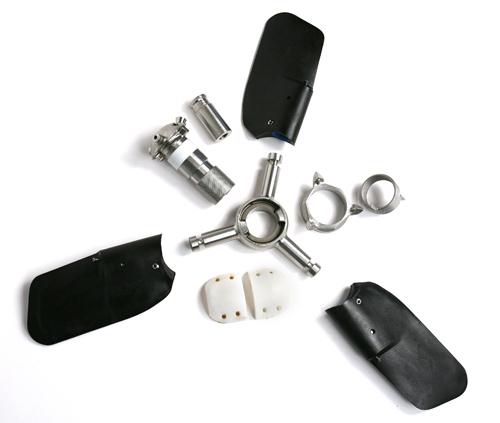
We have so far used 3 different types of saildrive boots with various levels of success. See Ocelot's saildrive boot solution here.
We are currently using the Yanmar factory rubber leg boot but added a ¼"x1.5" acrylic ring with 8 screws to hold it in place over the outer edge of the boot. This should be done with the screws drilled into the saildrive water chamber outer wall, which is solid 3/8" fiberglass, not the main hull which is foam cored. It provides a tight, flexible fit, keeping unwanted debris out of the water chamber while allowing smooth water flow over it.
Protecting the Aluminum Saildrive Leg from Your Bottom Paint
We think it is best to first coat the aluminum leg with multiple coats of epoxy or an epoxy primer and then use something like Micron 33 as antifoul for the aluminum legs. There is no reason to risk using a copper based antifoul paint on the aluminum leg.
Micron 33, though expensive, works very well as a multi-season antifouling coating. A quart will allow application of many coats on the relatively small saildrive legs. Our boots and the Micron 33 have been on now for about 3 years and many thousands of miles.
Diesel Engines-Bypass oil Filtration System
On the Perkins engine on the CSY, I used an Amsoil Bypass Filter that required relatively expensive filters. (CSY Amsoil Discussion)
On the new boat, I have fitted Jackmaster Oil Bypass Filters.
In order to add bypass filters to our diesel engine oil filtration systems, we chose the Australian Jackmaster units. They can use common toilet paper rolls as filters, which give .5 micron filtration and are changed about every 100 hours. Each filter change includes the addition of about one half liter of new oil with additives.
Advantages of bypass filtration include greatly extended oil change intervals, improved filtration compared to the factory full flow filters (.5 vs 10+ microns), and no need to carry or find gallons of oil for each oil change. A knowledgeable cruising friend has been using this system for years with no problems. Also see this testimonial about a truck that ran 1 million miles with only one oil change, using bypass oil filtration.
Synthetic Oil & Engine Oil Analysis
When we were in Florida, I used a lab in Atlanta called Power Trac to do my engine oil analysis (800-394-3669), but there are many others. Just stop by any large diesel dealer and they can sell you a sampling kit consisting of small double plastic bottles for about $12 US.
I take a sample about every 300 hours and send it in via any cruiser going back to the US. After a week or so they will send me the detailed computer printed results via mail, fax or my phone call. It's a great way to keep tabs on what's going on inside the engine.
Most major truck fleets and other multiple diesel users like the US Navy have been doing this for years. Oil analysis is part of what we called trend analysis in the Navy, and it was part of the engineer's work to monitor it.
In order to extend your time between oil changes, use synthetic oil, make sure you get a bypass oil filter to remove contaminants down to 1/2 micron and all moisture from the oil. Otherwise even though your synthetic oil's lubricity may be intact, and it should be for a couple of thousand hours, the oil will get overwhelmed by contaminants and water. My synthetic oil of choice is Amsoil.
In addition to the synthetic oil being better for your engine, the main reason I started using synthetic oil was to keep from having to carry the many gallons of oil I would need to change oil every 150 hours as engine manufacturers recommend. Third world oil is of questionable quality and very expensive.
Keeping Your Fuel Clean
It is a good idea to thoroughly clean the inside of your fuel tanks by hand rag about every 5 years. But, so far I have seen no way to do this on our catamaran! The fuel tanks are permanently mounted in a locker with no access port.
But so far we have had no fuel problems. We use a modern plastic housing filter (Mr. Filter), similar to what West Marine sells, to filter ALL fuel going into the tank. These have been tested to be better than the old and expensive Baja filters.
Filtering your fuel as you add it to the tank is the only way to make sure you are getting clean fuel and won't end up with contaminated fuel at the bottom of the tank.
We also use the Hammond Biobor JF and Lubribore products to clean and lubricate the fuel. These products only require a small amount to be added to every tank full of fuel, so a couple of quarts goes a long way.
Recommended Reading: Diesel Repair Manuals
(Topica Post 2004) Regarding good diesel manuals and obtaining advice I would recommend obtaining a copy of one of Nigel Calder's books: Marine Diesel Engines or Boat Owner's Mechanical and Electrical Manual. Look in Amazon.com. There are also others.
You should also have onboard both the Owners Manaul, the Parts Manual, and the Service Manual for your engine.
It's well worth doing your homework by reading these manuals and learning your engine before something goes wrong and you end up spending a great deal of money for someone else to fix it. Armed with the knowledge from these sources you will also be better able to seek and evaluate any advice you may obtain--including the above.
Copyright 2026
WebDesignsInternational