|
St Francis |
|

Last Updated: 10/10/2026
The electrical systems and issues on our previous boat, a 1980's CSY monohull, were quite different than those on our 2004 St. Francis Catamaran. For all the things I did over the years on the CSY electrical system, go to this link: CSY Electrical Systems. However, be aware that not everything at that link reflects our current thinking. Modern technology, especially Lithium batteries, has given us considerably better options.
In December 2024, we embarked on another major upgrade to our electrical system, nearly doubling our solar and adding 50% to our house battery bank capacity, plus adding additional components to comply with US ABYC electrical standards. As all things on boats, this is still a work in process, but below reflects our current status.
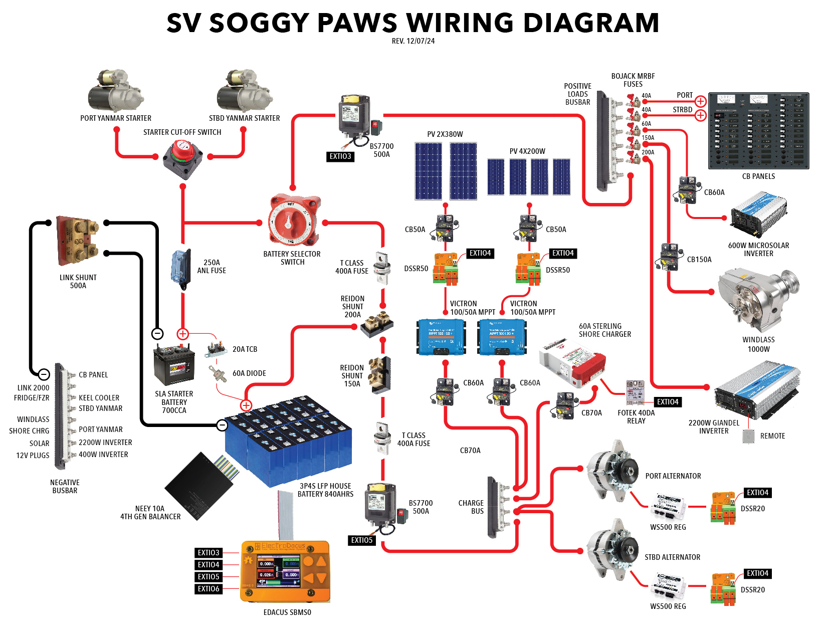
The major components of our DC system (Click for a
Larger Version)
See our recently compiled "ABYC Compliance Document" that refers to the safety features of our system. We wrote this up to be able to provide a document detailing the parts of our LifePO4 setup that provide the safety features required by ABYC and ISO. So far, our insurer isn't requiring anything like this, but we wanted to get it all documented while it was fresh in our minds. And this document and the wiring diagram above provide a good overall summary of our current electrical system.
Upgrading to Lithium - Cost of Doing it Yourself vs Hiring a Paid Electrician
If you are contemplating building a Lithium Iron Phosphate (LFP) battery upgrade on a boat, following the below information, and doing the work yourself, know that the total cost should not exceed about $2500 US for similar sized bank, cells, BMS, wiring, fuses and shunts, wire terminals and cell connectors, basic tools and test equipment. However, additional costs that might be required include replacing some of your older equipment, including chargers, solar systems, inverters, monitors, etc.
If you have a qualified marine electrician do the work, it can easily double or even triple the cost, especially if done in the US and using "Drop In" LFP batteries. In 2020, we studied the technology and systems options first for about 6 months before proceeding as neither of us are degreed marine electricians. Then we followed what several others of like mind were doing. Some of that worked well and some not so well. Since then we have learned a good bit more as technology and equipment have improved greatly. In particular Grade A cells now cost about one third what they were in 2020 and the quality has improved considerably. Posts and videos of these improvements are all over the internet with some of our favorite trusted sources listed at the end of this article. No one should start this project without a thorough understanding of the current state of the technology and the various equipment options available. However, using the trusted information now on the internet almost any reasonably capable cruiser should be able to execute a safe LFP system on a cruising boat.
Before beginning several major decisions must be made. They include:
- Whether to use premade ‘Drop In’ batteries or make a battery from multiple cells
- Whether to use an external relay or internal Mosfet Battery Management System
- How do I wire the batteries: in parallel or series
- Whether to use compression on the battery or not
- Where to place the battery box
- How to keep the cells and batteries balanced
- How much of your charging and other equipment must be replaced
- How to protect charging equipment from a sudden battery disconnect
- How to charge the starter battery
- How will you wire the new battery system in your boat
- What additional tools and test equipment to buy
- How to precisely monitor the battery status
- Ensuring ABYC/ISO safety compliance standards are met
Lithium LifePO4 Battery Upgrade, 2016-2026
When we purchased our St. Francis 44 catamaran in 2015, the house bank consisted of six 6-volt Sonnenschein Solar Block 200 batteries, for a rated total of 600 Ahrs at 12 volts. However, as with all lead-acid batteries, the useable capacity was less than 50% of that. Even though they were very high quality German Gel batteries.
In early 2020, locked down by COVID in the Philippines, and with our Gel battery bank then 13 years old, we decided it was a good opportunity to install new lithium battery technology. The Gels might have lasted several more years according to Gel literature, and because of the quality charging equipment we had, but given our location in SE Asia, and the time we had available, this was a good opportunity to upgrade.
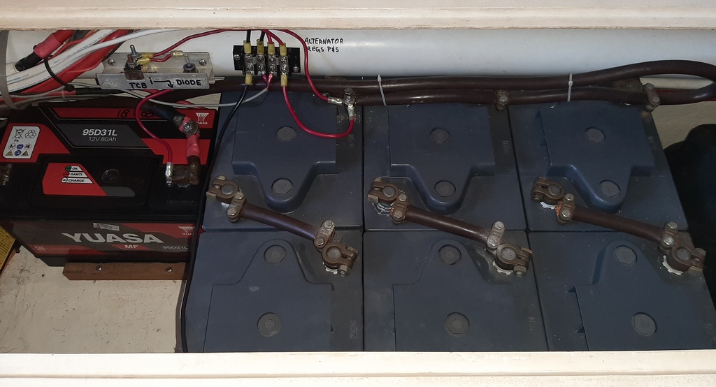
Our 700 CCA sealed lead acid start battery on left and original 390 lbs/175 kilos of
Gel batteries right.
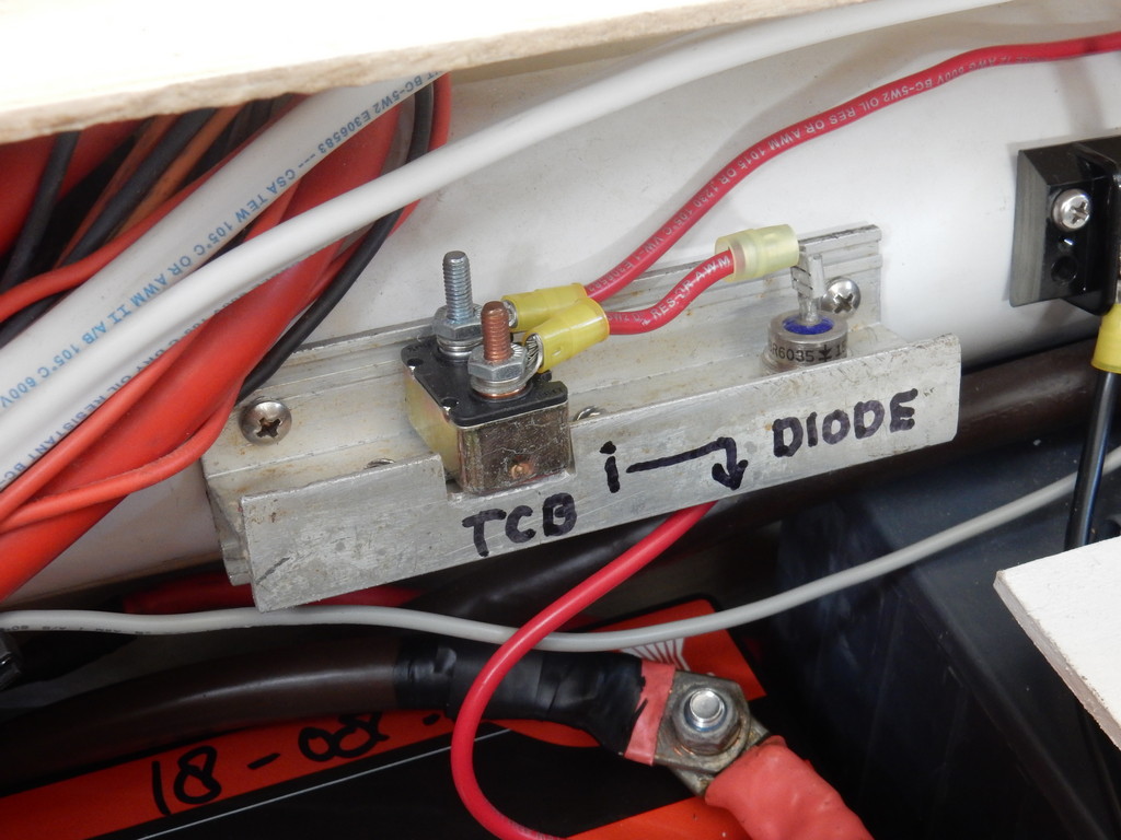
TCB and Diode on aluminum heat sink above the start
battery are for trickle
charging start battery off the Gels. More about
this.
Our installation is optimized for a catamaran cruising full time overseas. We have little tolerance for jury rigs, marginally safe practices and unnecessarily high cost equipment. We believe that if installing lithium on a cruising boat, it is worthwhile to develop the skills to install and make repairs ourselves with adequate spares and proper tools onboard.
Even if you use an experienced electrician to do the installation for you and watch his work carefully, without your own study before he starts, it will be very difficult for you to understand what he is doing and why. And he will do the install his way, which might not be the best way for you and your budget and cruising plans.
There are many ways to do a Lithium battery install and a multitude of equipment choices, some much better than others for full time cruisers. And then there are your insurance considerations and ABYC/EU/etc recommendations to consider. So you need to be involved in making that decision for your own safety.
Had we not had the time to study the technology, place the orders, and make the necessary electrical system changes, we would not have taken on this project. It is not a project for those not willing to spend time learning how to do the installation properly.
Basics: Making the change to LiFePO4 (LFP) batteries has a number of significant advantages, but may require some expensive equipment changes in addition to the new equipment you install. All this needs to be evaluated before the LFP install begins, or you may make serious mistakes. Best to work out a wiring diagram as we have shown above before beginning work.
LFP technology suitable for cruising boats consists of an appropriate number of individual prismatic 3.2 volt cells that operate safely within a narrow voltage range. Straying beyond this range can cause permanent cell damage or loss of service life. Using preassembled "Drop In" batteries that have inaccessible and unknown equipment inside, with no or inadequate monitoring communications via Wi-Fi or Bluetooth, is a recipe for disaster. Drop In batteries are also very expensive compared to using individual prismatic cells for your house bank.
For a Best Practices LFP battery system: A boat's electrical system should have separate charging and load busses wired to a single house bank through appropriate shunts and fuses.
Each of the charging sources (solar, alternator, shore, etc.) should have a relay or direct connection that allows an external relay type of Battery Management System (BMS), monitoring individual cells, to shut it down, not just disconnect it from the battery. This should happen automatically if there is a problem beyond what the charging device (solar, alternator, shore charger, etc) does with its own onboard charge termination. Internal Mosfet relay BMSs, now in common use (especially by marine electricians), disconnect the battery from the rest of the electrical system, which may be problematic on a cruising boat, and should be carefully evaluated. The reason that installers are choosing the "internal mosfet relay" BMS's is because they are easier to install, requiring less installation and wiring time for the installer.
In normal operation, the onboard charging sources' regulators, reading only total battery voltage, should control the charging and charge termination using mainly the bulk phase with no, or only minimal, absorption. The BMS, which can read individual cell voltages, then acts as a backup to terminate the charge at the High Voltage Disconnect (HVD) set point if a single cell's voltage gets too high, and the charging source fails to terminate the charge in time.
There should also be a relay or relays on the major load buss equipment, for the BMS to similarly disconnect loads at Low Voltage Disconnect (LVD) if the battery or cell reaches too low a state of charge. This needs to be carefully set up AND TESTED--you don't want an automatic disconnect of the load buss to occur in, for example, a critical navigation situation.
An additional safety feature would include bigger relays that could shut an entire load or charge buss off from the battery as an ultimate safety feature. However, not all external relay BMSs have enough external control outlets to accomplish this.
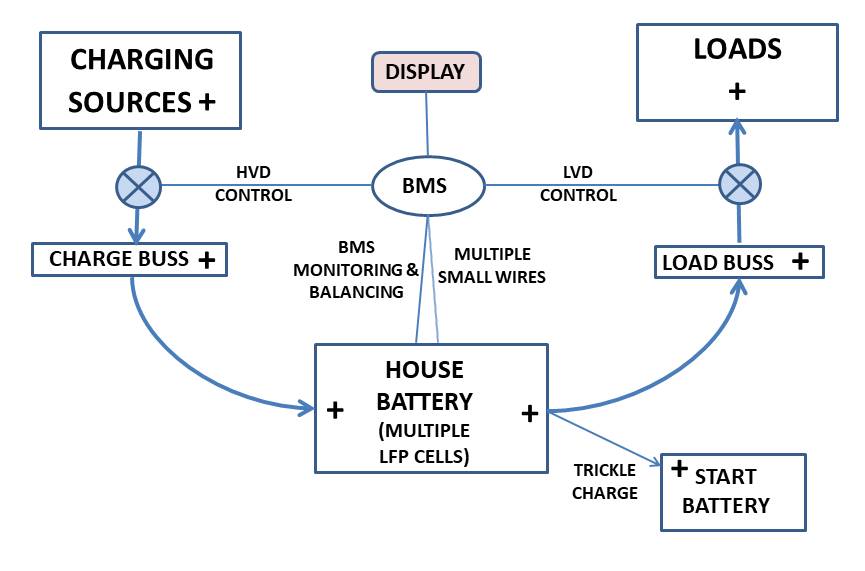
Very basic LiFePO4 battery wiring diagram with BMS and separate charging and load busses. Fuses, shunts, relays, etc not shown.
After significant research and living with the new technology now for over five years, below find our thoughts on how to choose equipment and complete a DIY LiFePO4 lithium cell installation on a cruising sailboat.First here are some cautions:
- The technology and supporting equipment are still evolving, with a multitude of choices available, some much better than others. Quality of equipment is an important issue, not only with lithium batteries and cells, but with all equipment used on a boat. See our slide presentation on equipment options and advice, here.
- No serious cruiser should change from lead acid to lithium batteries unless they are willing to spend a substantial amount of time in research, effort, and money to do a proper installation.
- There are many opinions regarding how best to do this; even the experts' opinions differ. And, there are substantial differences in "best practices" between off-grid homes, RVs, electric vehicle (EV), and marine installations. But there are several trusted information sources. See the list at the end of this article, here.
- For a marine installation, especially if done by a professional installer, where you may have to perform adjustments or repair after he has left, it is crucial that the cruiser have intimate knowledge of his/her installation, and its equipment.
- Competition among sellers of lithium equipment is stiff, especially among cell and BMS producers. US and European distributors can be significantly more expensive than purchasing cells direct from the manufacturer, usually in China. However, several large cell producers like EVE in China now have trusted distributors with convenient warehouses in the US and Europe.
- Not everything you read on seller websites is true, and some important things that are not there are true. Having a close look at specifications and warranties is very worthwhile, especially if you have a problem.
- Communication with an online seller is important. Some are much better than others. See the Lithium forums for real time experiences of those that have made recent purchases.
- In order to create a successful installation, you must have an open mind and be curious about what has worked and not worked for others.
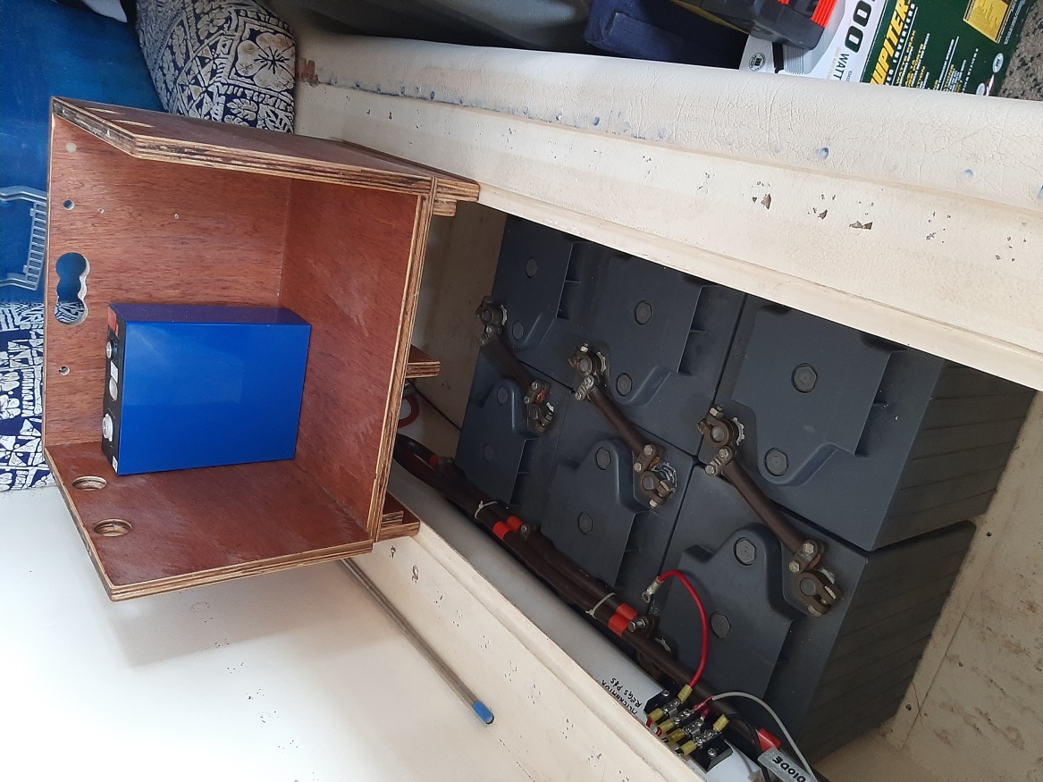
Replacing our LA Gels with blue LiFePO4
lithium prismatic cells.
Above: Six 6-volt Gels, but only one of 8 LFP cells is shown.
Four of the 3.2-volt LFP blue prismatic cells can produce as many amp hours
as all 6 Gel's (shown) together,
and only weigh 44 pounds.
Lead Acid (LA) vs Lithium (LFP) Differences: Because of the vast differences between these two types of batteries, great care must be taken to not make a mistake during planning and installation. A number of different Lithium ion type cells are available now, but LifePO4 is the choice for cruiser batteries. It has significant advantages over the others, including being reasonably safe and stable in a marine environment. Even some of the electric vehicle companies, like Tesla, are now changing to LFP. Despite what you may have read elsewhere, there has never been a self-ignited fire in an LFP battery. However, improper wiring or shorting of LFP batteries, which can produce very large amounts of instantaneous current, have created fires in the wiring or surrounding flammable material. If ovecharged, LFP batteries can develop thermal runaway, but will not catch fire.
Below are some differences between LFP and LA technologies:
- LFP cells do not require a full charge on a daily basis; in fact, charging to 90%, or even less, is perfectly acceptable and may give a slightly longer service life. This is a huge advantage as top-ups to full charge are not required on a daily basis.
- With LFP, no absorption or float charging is needed, only bulk. This means that once the bulk charge is completed, the charger can be turned off. But not all older marine Lead Acid chargers can do this. And automobile chargers are not safe on a boat due to their internal wiring.
- LFP typically have fifty percent more usable capacity for the same overall rated capacity. 80-90% of LFP rated capacity is useable on a regular basis vs a maximum of 50% for LA but under ideal conditions.
- LFP service life is now typically 3000-8000 full cycles vs 500-1000 cycles with LA.
- Cell level monitoring, balancing and disconnect control are required with LFP, whereas only those for the total battery are typically needed during charging with LA.
- There usually are some significant electrical system modifications required for a proper LFP installation. These include purchase of a quality and reliable BMS, installing separate charge and load busses (connection points), fusing upgrades, monitoring upgrades, and using separate inverters and chargers.
- Charging with an alternator requires some modifications, or you risk over heating your alternator internals. You must either make sure the alternator is externally controlled by a smart alternator regulator with temperature monitoring and reduced output control, or use battery-to-battery controlled charging, possibly with a lead acid battery also connected to the alternator. In all cases, the externally regulated alternator is much preferred, for charging efficiency, especially on a marine engine charging system.
- Batteries made of LFP cells are about one third the weight and take up two thirds the space of LA batteries. They can be charged significantly faster and have little voltage drop when placed under a heavy load.
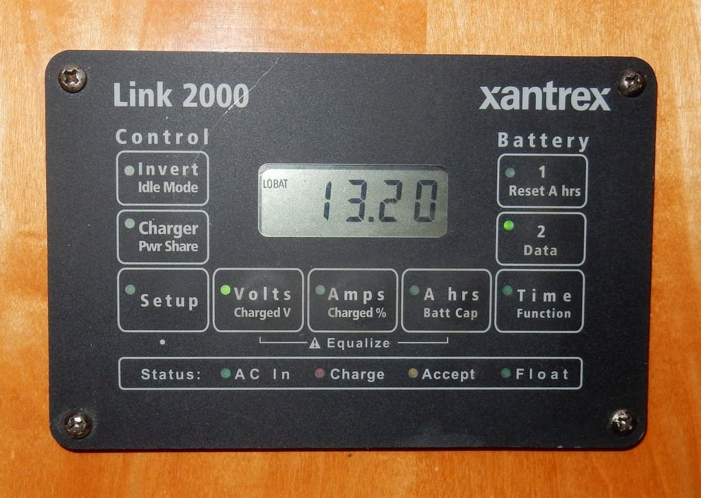
Our older Xantrex Link 2000 LA battery monitor that displays only total battery parameters.
Do It Yourself (DIY) LifePO4 Cells: After a great deal of research, on our first go-around in 2020, we settled on prismatic-style aluminum-cased individual LifePO4 cells, purchased directly from RJ Lithium in China (our 2nd batch of cells purchased in 2024 were purchased from a different company, keep reading for details). There are a number of other Chinese cell companies we could have bought from, but other cruising friends locally had researched this and were buying from RJ. Their reputation was good, they offered documented Grade-A cells, the sales representatives were responsive, the website was informative, and they offered a 5 year warranty.
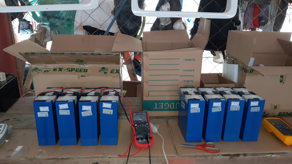
All eight of our original cells with taped terminals and typical Grade-A labels, just out of the shipping boxes
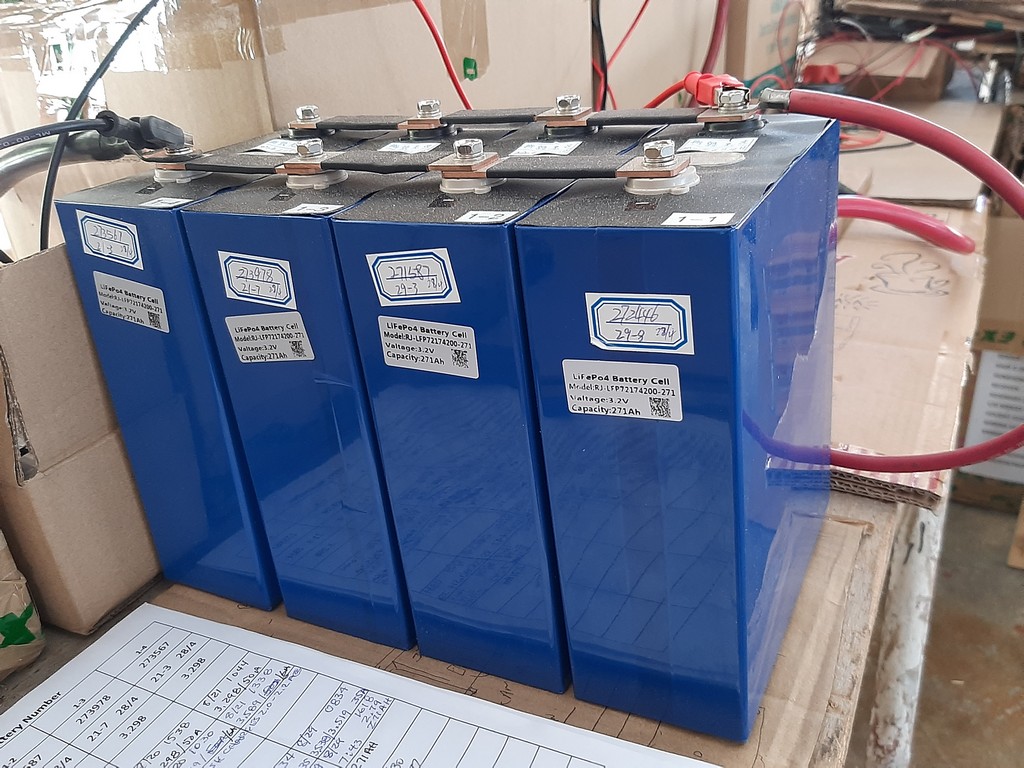
Four of our 2020 prismatic cells with Grade A
testing stickers intact
tested capacity,
voltage, serial number and manufactured date.
We purchased eight 3.2 volt 271 amp hour (Ah) LFP cells, for about $150 each plus about $35 shipping each for a total house bank capacity of 542 Ah. (Note that the shipping cost was extremely high at the time, due to the peculiarities of shipping into the Philippines via Hong Kong).
Our purchase of 12 new cells in 2024 was much more reasonable--approximately $50 USD per cell, and $300 USD for air freight from China to Malaysia.
Of that 542 Ah, more than 450 Ah are useable, so we increased our capacity by about 50% over our Gel bank's useful capacity. And we were able to remove 390 lbs of Gels and replace with only 100 lbs of lithium cells.
Later we discovered that we could have bought similar well-regarded EVE or Lishen cells for $100 USD each and modest shipping cost, sourced locally in the Philippines, but without the longer warranty. So our cost for the RJ cells was about $1500 US including shipping. Lishen or EVE cells would have been around $900 including shipping. (Our 2024 12 x 280 Ah EVE cell purchase cost $1160 USD, including the cost of air freight to Malaysia.)
The LFP cell market is constantly changing, and competition is fierce, so this pricing from China may change in the future. On the LFP forums we have seen these Grade A cells being shipped to the US and Europe at very reasonable prices. A cruising friend in our marina in the Philippines in early 2022 purchased 240 Ah Grade A EVE cells with a 2 year warranty and minimal shipping for about $100 US each.
In late 2024 we discovered problems with our RJ cells related, we think, to poor cell matching at the factory, large differences in internal resistances, weak BMS balancing capability, possible additional cell connection resistances due lack of proper terminal torqueing and some problems with combining solar and alternator charging sources. About half our RJ cells had bulging sides, and others exhibited unusual charge and discharge characteristics.
So in Dec 2024, we purchased 12 very high quality 280ah cells from
Docan Power, a very
well respected reseller of EVE cells based in China, with several warehouses
in other countries. This will increase our rated LFP capacity from 540 Ahrs
to 840 Ahrs. These cells are matched by Docan Power to have internal
resistances within .01 milli-ohm and voltages within 1 millivolt at about
60% shipping/storage state of charge. They are the latest generation with
stud terminals and are priced at about $55 US each, plus shipping. These
prices reflect the high volume of cells now being produced in Chinese
factories. They also have a 5 year warrantee! And, they have a US warehouse,
so if you are in the US, ground shipping is very economical!
Drop-In LifePO4 Batteries: As previously mentioned, we do not recommend installing what is commonly referred to as "Drop In" lithium batteries on a serious cruising boat. They are better suited to coastal power boats, outboards, and land-based off-grid installations for the following reasons:
- Especially with inexpensive makes, the cells and BMS are often secured inside a sealed battery
box and may be inaccessible if there is a problem.
- Typically, the BMS provided uses small internal MOSFET relay components that must control the high currents usually found on cruising boats. If anything goes wrong, the owner may have to replace the entire battery and BMS, at great expense for both the battery and shipping.
-
- There may be little adjustment available to the charging and
other control parameters which you may want to customize for your
installation and longer service life.
- External communications via Wi-Fi or Bluetooth for monitoring and
control may be limited. This is a critical component of the system and
must be rock solid.
- Through a dealer they can be frightfully expensive compared to a DIY
installation using individual cells and separate quality BMS.
- You will still need to do many of the same modifications to
your electrical system as with a DIY system.
If you can't take the time to do a proper DIY installation yourself, or with help from a knowledgeable friend who will teach you the mechanics and options, we recommend buying quality Gel batteries to install into your existing LA electrical system.
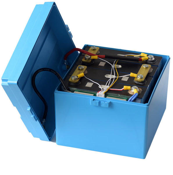
Four 3.2v LFP cells with MOSFET BMS, wired in series inside a 12v pre-assembled/"Drop In" battery case. (source: RJ Energy)
Charging and Discharging: The LFP cell charging curve is very flat in the middle between 3.20-3.4 volts per cell (Vpc). Then it goes nearly vertical (commonly referred to as "the knee") as the cell approaches full state of charge (SOC) at about 3.45 Vpc and above. Because charging through the upper knee takes only a few minutes, it represents very few Ahrs and may not be really necessary. Likewise, as the battery is discharging, the voltage stays very flat until dropping off rapidly below about 3.15 Vpc as the battery reaches 10 percent SOC (see graph below). The relatively high stable voltage and flat discharge curve are a big help when using high amp draw equipment like an inverter, windlass, or galley appliances.
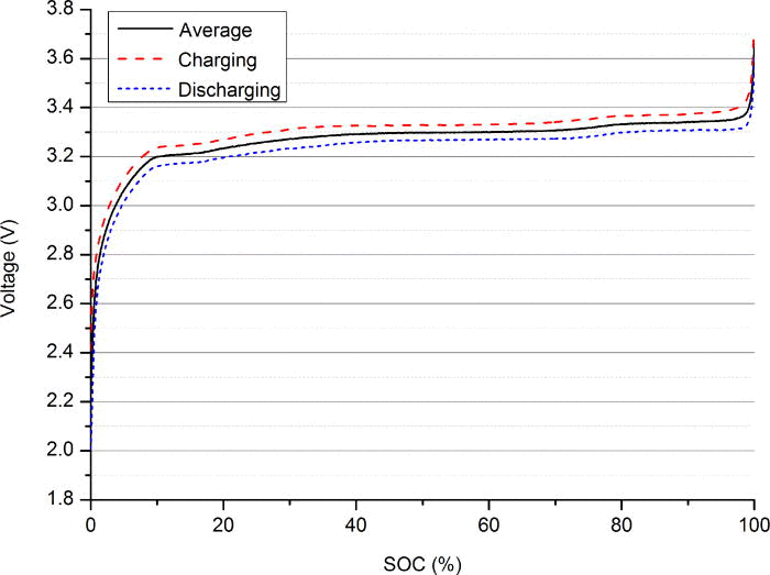
LFP Charge and Discharge Curve comparison
Graph courtesy of
Energie Panda, a
supplier of high quality LiFePO4 cells for DIY LiFePO4 batteries
Cell Matching and Balance: Factory matching of cell capacity and internal resistance are important for being able to maintain cell voltage balance. But it is a labor-intensive, and therefore expensive, process, so discount cell companies selling cells at very low pricing are not able to do a good job.
Several companies, like Winston and now EVE/Docan Power and maybe a few others, do better matching work. This is reflected in their relatively higher pricing. If you have purchased discount cells (not recommended), this is where a good active balancer in the BMS (capable of several amps or more depending on the size of the bank) or a separately-purchased quality active balancer, like the NEEY, earns its keep.
If the cells are not reasonably well-matched in capacity and very closely in internal resistance, when charging, one cell can get to 3.65 Vpc well before the others. This is an over voltage situation that can destroy that cell before the total battery voltage reaches an alarm condition. Likewise, when discharging, if one cell is slightly more depleted than the others, its voltage can drop rapidly to below 2.5 vpc, a destructive under voltage situation, again while the overall battery voltage is still at a safe level. A quality BMS that can monitor cell voltages can control these situations through relays and prevent cell damage.
Also, cells that are not well matched for internal resistance will have
slightly different charge curves that might cause an automatic balancer to
balance the wrong cells during charging. Our original RJ cells were not perfectly
matched, so their charge curves intertwined voltage levels as they are being
charged. Sometimes the low voltage cell at the start of charging becomes the
high voltage cell at charge termination. A good active cell balancer of at
least several amps can handle
this and keep cell balance levels within a reasonable delta of about 10 mV
or less.
Cell Grading: Well-regarded lithium factories produce thousands of individual cells a week. During initial testing, those that match advertised specifications are graded as A cells. Those that do not become grade B cells and could have a range of problems. Both are sold on the open market. Grade A cells are usually a bit more expensive, have QR and testing stickers intact and usually have warranties of a year or more. Grade B cells are often sold to off-grid applications that use hundreds of cells so that they can afford to have a few that have problems. They are also sold off to discount retailers like Shopee and Lazada. Serious cruisers would do well to always buy matched Grade A cells as it helps ensure full usable bank capacity and makes balancing much easier.
Even after being assured we had Grade A cells, and doing exhaustive testing upon receipt, we ended up with one bad cell that would excessively self-discharge compared to the others. It lost a half millivolt (mV) at rest on a daily basis, which resulted in it quickly falling behind the others at charge termination. This is one symptom of a grade B cell. It is extremely rare for quality cells to have a problem after the first 6 months of service life. So early on is the right time to identify any cell problem.
To their credit, RJ replaced the cell under warranty with us only paying the $20 US shipping cost. Meanwhile, we purchased two similar Grade B Lishen cells from an online source in Manila. They performed well, but we eventually went back to using all RJ cells in our house bank. The Lishen cells were kept as spares. As we all know, cruisers can never have too many spares.
Configuration: Banks of lithium cells are typically connected in sets of four 3.2 volt cells in series for a nominal 12 volt battery system. If you have a 24 volt electrical system, connect 8 cells in series. For more capacity than 4 or 8 single cells will allow, first connect cells in equal parallel sets, then connect those sets in series. The parallel sets can be comprised of various capacity cells, but the series sets must all be of equal total capacity and voltage.
We originally planned to configure our 8 cells into two 4-cell "batteries", with a 1-2-Both selector switch so we could switch between batteries if we ran into a problem with one battery. However, once we started wiring up the two Electrodacus BMS's, we found that trying to control the separate loads, charging sources, 2 busses, and multiple external relays with two BMS's became impossible. Most internal relay BMSs are able to do this effectively. If there is a problem they disconnect their individual battery from the system and the other battery can continue on. However, there are some wiring complications and often battery balance problems between individual batteries. We also realized that if we ever ran into an extremely rare cell problem, later on, rearranging the cells with our spares to make repairs would be a pretty simple solution. Once past the "infant mortality" stage, if there is a problem with the cell it rarely happens suddenly.
So we originally ended up with 4 sets of 2 cells in parallel to make 4 "supercells", then those 4 cells in series for a 542 Ah at 13.2v bank. This also had the advantage of requiring only one BMS instead of two, and only one compression box. Since we had ordered two BMSs we now had a spare. And as all cruisers know, you can never have too many spares.
Whether our configuration is called 2P4S or 4S2P configuration depends on who you ask. It is written both ways all over lithium literature and the internet. So be mindful of this when asking questions on lithium forums. Sometimes it is preferable to better describe your configuration rather than using one of the above abbreviations and causing confusion.
2024 Update: Now that we have twelve 280 Ah cells we have constructed a new solid fiberglass box with compression for 3 cells in parallel instead of two. The connections to the twelve cells are similar, but for twelve instead of eight cells.
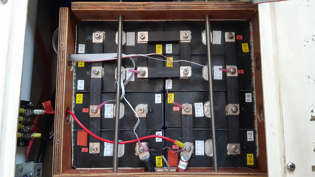
Our original 8 LifePO4 cells in their compression box in a
2P4S configuration. Two of the four threaded compression rods are visible in
place. Flexible connecting straps are made of multiple layers copper
carefully cleaned and firmly fastened to the terminals.
The small grey ribbon
cable wiring is for the BMS monitoring and balancing functions.
Cell Compression: Most literature and experts on LFP cells recommend using a 'compression box' to house the cells. This is more of a 'limitation box' that prevents the cells from chafing against each other and shorting, terminals being damaged by connector tension as a result of expansion during charging, and sliding around as a bank in rough weather. According to EVE Energy, one of the largest lithium cell manufacturers in China, their aluminum case cells require compression in order to reach their full service life, and prevent bulging. Many others agree.
So we originally built a compression box to store the cells using epoxy-coated 3/4-inch marine plywood and 3/8-inch Stainless Steel threaded rod. Between the cells we used 1 mm soft placemat material to prevent the cell sides from shorting together and provide somewhat of a cushion. The box has a polycarbonate cover and is strongly secured under our main cabin settee in the middle of the boat. It is only about 3 feet from the BMS, busses, regulators, relays and other major wiring. The addition of calibrated springs on the threaded rod would allow us to control the amount of compression, but we think that is overkill. With more effort/expense, the compression box could also be made of fiberglass, aluminum or steel.
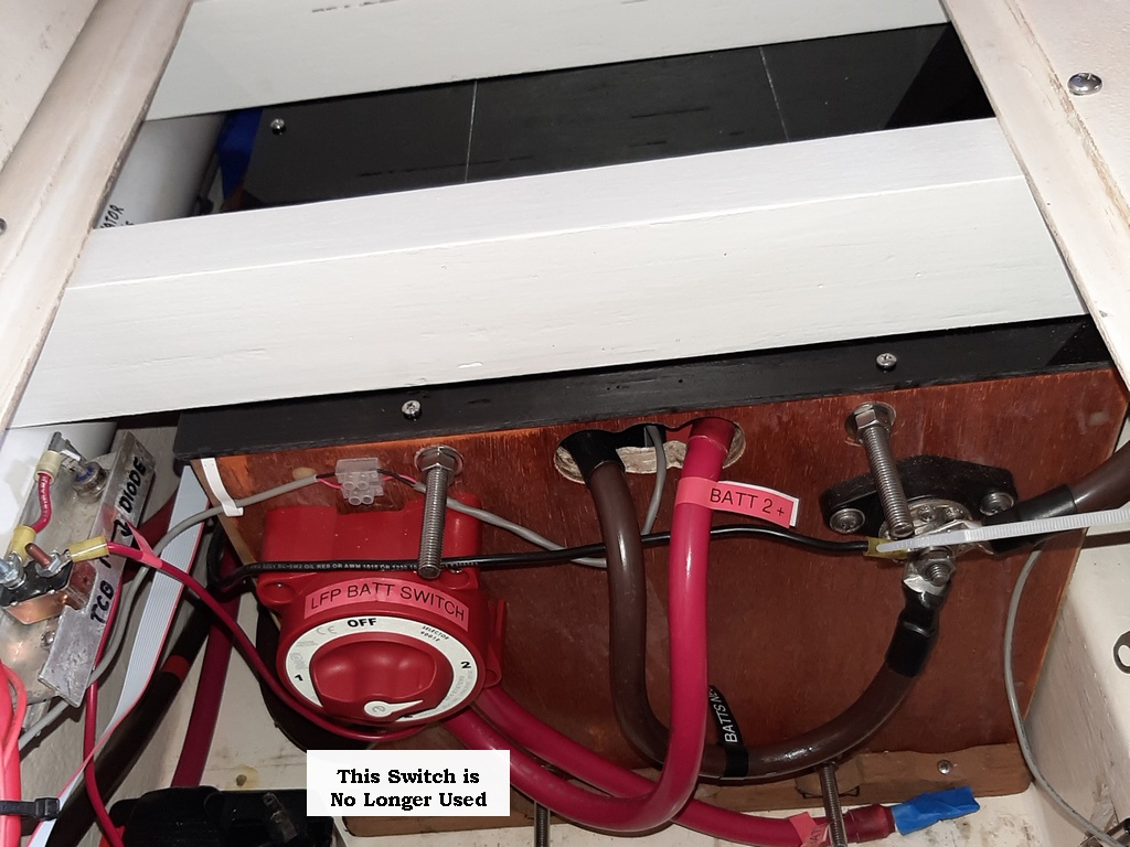
Front of our old battery box, with cover on and secured
under the settee seat.
Four threaded compression rods are visible in place.
Red large cable is positive and brown negative.
Thermal circuit breaker and diode on left are for trickle
charging the starter LA battery.
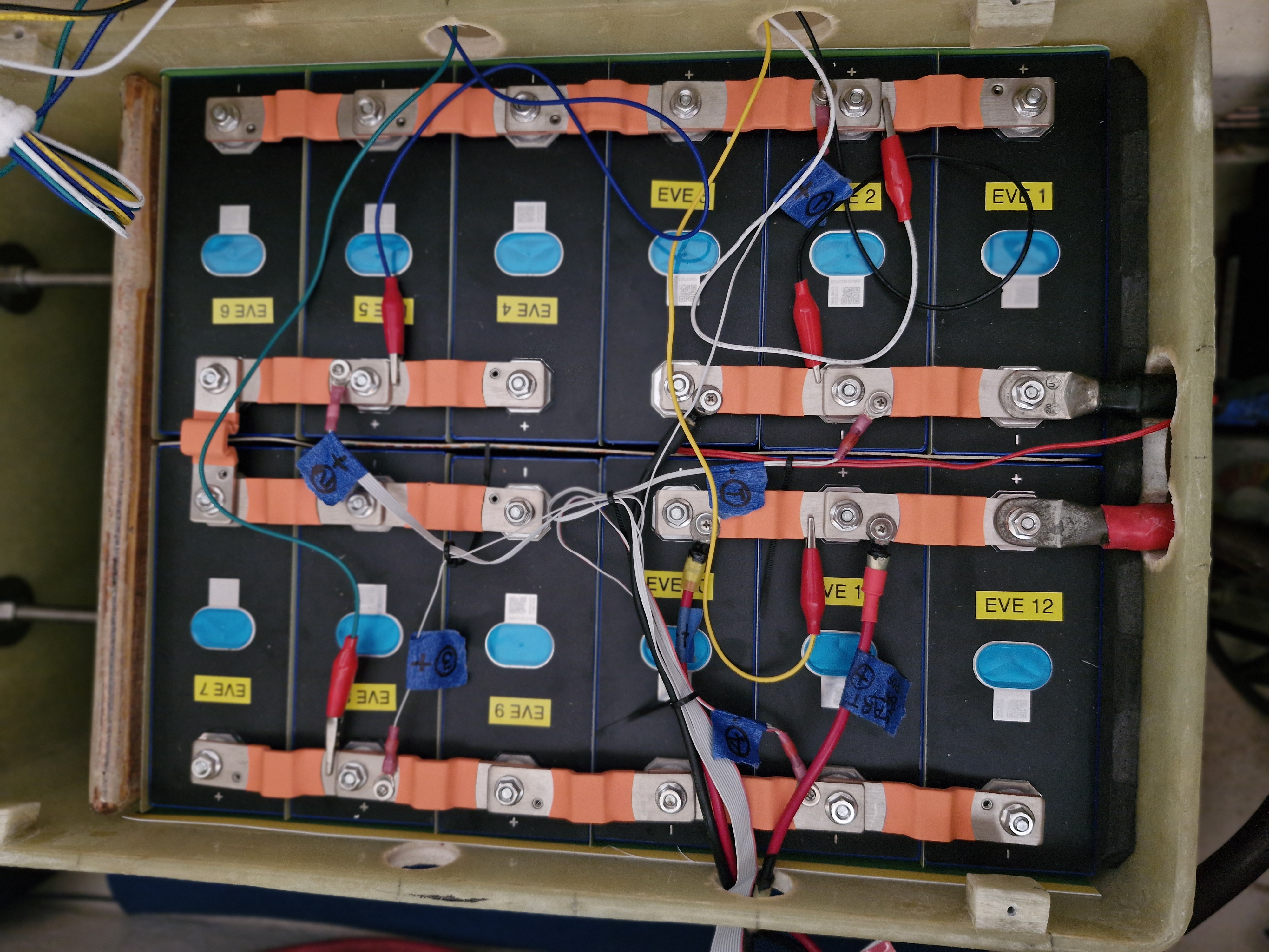
The new fiberglass box with twelve cells.
Its compression system
(top) consists of a plywood plate being
pushed into the sides of the two strings of cells by 4 pieces of threaded
rod.
Battery Management System (BMS): A good capable BMS is a critical component of a LifePO4 system. Unlike most lead acid battery monitors that display overall battery voltages, a good BMS should monitor individual cell voltages. So, as an example, an external relay capable BMS can watch the voltage and state of charge of each cell, and make appropriate decisions regarding when to disconnect charge sources in case of an over voltage event (HVD) or disconnect loads in case of an under voltage event (LVD) in order to prevent cell damage.
As mentioned above, there are two types of BMSs. One uses small internal MOSFET relays to disconnect their battery when required. They are typically rated for the expected maximum current in the system, and are frequently used in multi battery systems. Daly and JK are leading suppliers of these BMSs. The other type of BMS can control much larger external relays. Since loads like inverters and windlasses and charging sources like alternators and generators might involve relatively high currents, cruising boat systems are better done with a BMS that uses high capacity external relays, so internally it never sees high currents. REC, Orion and Electrodacus are the well- regarded suppliers.
An important BMS feature is its ability to display externally what it is doing and important battery details such as voltage, current and SOC. Options include hard wiring to a display device such as a computer, Wi-Fi, and Bluetooth using an application. We are using Wi-Fi so that we can see what is happening with our system when on or off the boat, even when halfway around the world from our boat.
Also, a good BMS will have some sort of cell balancing capability. 200 milliamps passive balance is the absolute minimum to keep most well matched and balanced marine house banks in line. Although as we found out, it was not sufficient to keep our initial cell set in balance. Many older BMSs use some form of low current passive balancing. Newer BMSs use up to 5 amp active balancers. Larger active balancers with up to 15 amps are available. Active balancers work with large cell deltas more quickly, removing excess amp hours from high voltage cells and place it in lower cells.
BMSs range in price from cheap/dumb $15 USD small open boards with no user interface, to high-quality programmable BMSs, for about $600 USD, that will integrate seamlessly with existing proprietary equipment like smart Victron components. High price doesn't always give you equipment with features you may need, but better quality BMSs are usually priced over about $150 US. Before purchasing a BMS you should look at the several internet sources for comparing BMSs, including user forums and YouTube videos. Just remember serious cruisers cannot afford unreliable gear, so paying for reasonable quality and reliability is worthwhile. But there is no need to go overboard for capabilities you don't need.
|
Our Electrodacus SBMS0 and its main monitoring screen, one of about two dozen screens available for monitoring and parameter adjustment. This screen shows, among other things, cell and total voltages, charging and load amps, maximum cell delta and SOC. |
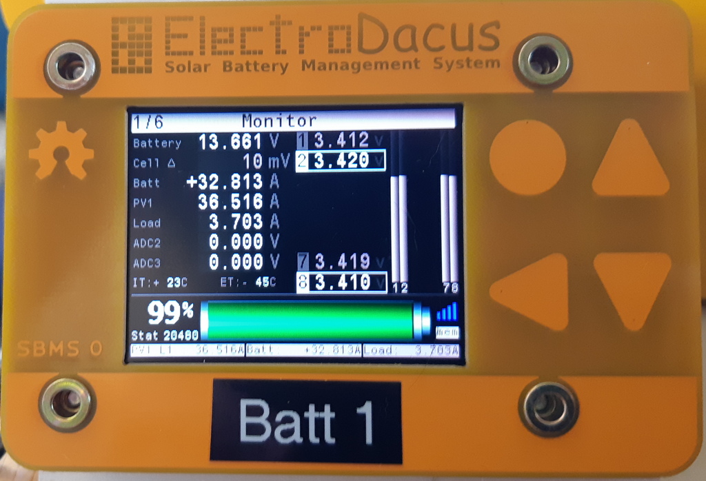
The Electrodacus SBMS0 also has excellent built-in historical logging, and with the addition of the optional Wi-Fi module, can provide a wireless MQTT feed to integrate into any Internet-of-Things (IOT) system. The MQTT capability allowed us to build a custom monitoring and logging screen (below), running on our Windows 11 navigation computer, and can also be configured to run on a Raspberry Pi.
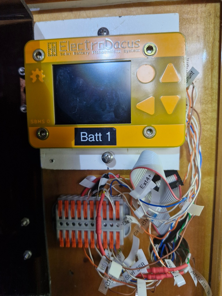 The ElectroDacus SBMS0 with new control wiring with orange/gray level connectors, mounted near our boat's navigation station |
With this setup, internet access, and a bit of free software, we can monitor our electrical system from anywhere in the world. There are also other ways to take advantage of the Electrodacus Wi-Fi option to create a monitor display.
What our current monitoring screen looks like (click on the picture for an enlarged copy):
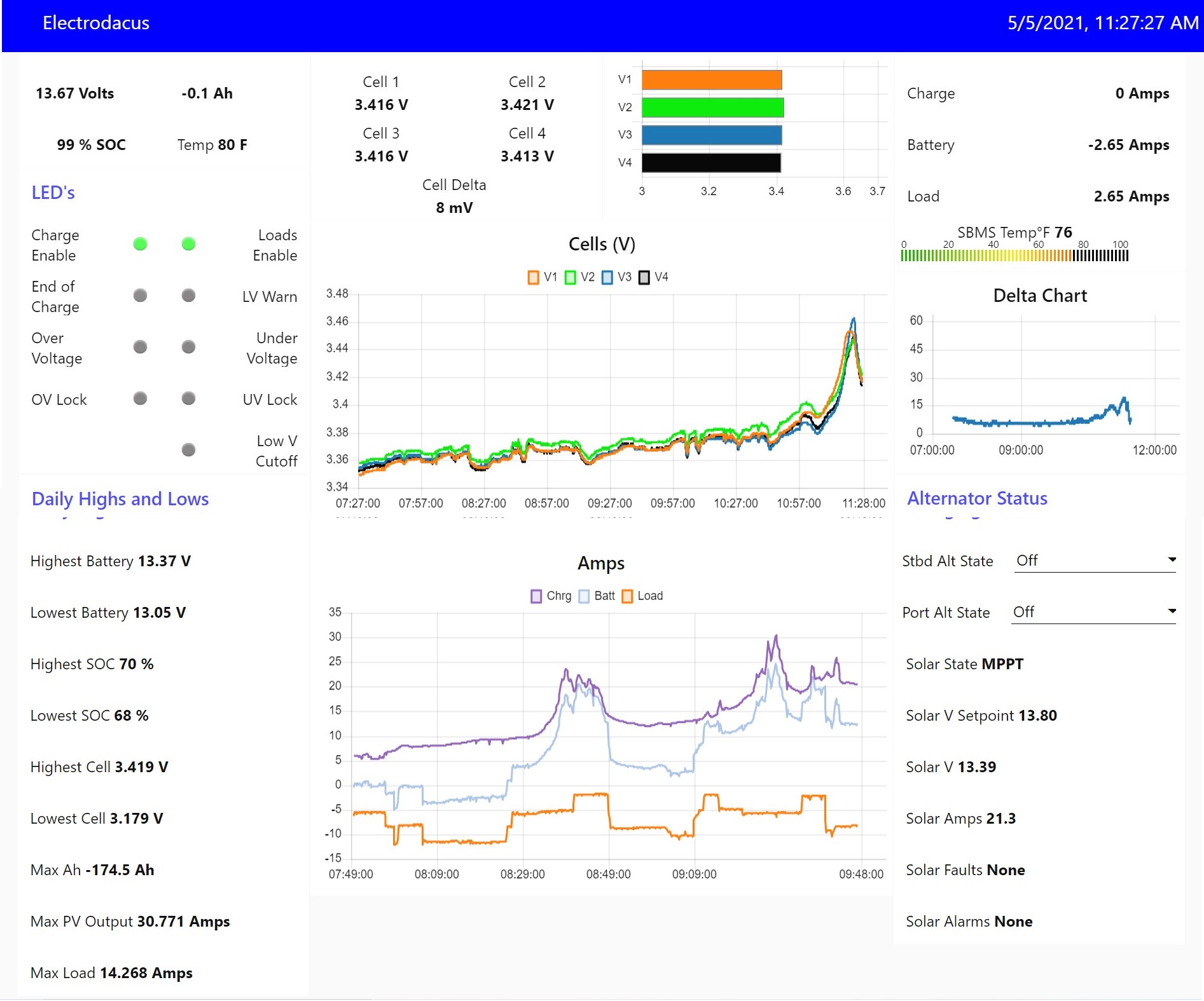
Our Battery Management monitoring screen,
using the MQTT feed from the Electrodacus, and built using Mosquitto and
Node-Red.
This is under constant revision by our onboard IT person,
Sherry.
(More
details about this)
We are pleased with our choice of BMS, but it has involved a steep learning curve. (LifePO4 in general is a big learning curve!) Considerable help is available from the detailed SBMS0 User Manual, an even more helpful user-built Beginner's Guide, two forums with experienced users and the developer, Dacian, answering questions. Dacian will even diagnose problems and fix them if necessary, usually at no charge regardless of cause, if you send the unit to him in Canada. Not many other electronics companies will do that!
Wiring & Fuses: It is important to use proper wire sizes, quality terminals, and make good connections, because proper monitoring and balancing involve millivolts and milliamps (thousandths of volts and amps). Any weak connection causing increased resistance will affect readings and function.
The display and balancing wires are typically 20 gauge or smaller, so you might need better crimping and stripping tools. For example, the ElectroDacus system uses twisted solid Cat 5 or 6 24 gauge wires for connections to the SBMS0. Common stripping tools won't strip those small wires. (See our tool recommendations below).
For our current marine installation we have changed to use 22 ga Plusivo colored tinned, multistrand wire instead of the Cat 5/6 solid core wire, because it conforms to ABYC standards and is much easier to deal with.
Fusing and circuit breakers must be of quality construction and function, placed where required, and of proper size and type. As an example, only a Class T or equivalent fuse should be used in the main battery cabling if the LFP battery is over 200 Ah capacity. No other type will do. These LFP batteries can produce huge amounts of amps, up to 20,000 A instantaneously, if shorted. Although LFP batteries don't themselves catch fire, a shorted cell can melt tools instantly and cause wire sparking and fires in nearby flammable material that can ruin your day and your boat. Proper installation will also prevent disapproval of an insurance claim should something go wrong or other lithium equipment cause the fire. It is also worth checking your insurance information to see if there are any specific clauses about LFP batteries. The US-based ABYC and EU-based () has recently released recommendations that we expect insurance companies to begin citing in their coverage of boats with lithium battery systems.
Relays & Shunts: When using a BMS capable of controlling external relays, care must be taken regarding which relays to use for which circuits. And quality shunts must be used in order to display accurate current flow and State of Charge (SOC). Below is a list of those we used:
- Solar charging: In case a High Voltage Disconnect (HVD)
event occurs, we originally used two of the ElectroDacus
DSSR20 relays for the SBMS0 BMS to disconnect the four 200 watt panels from MPPT solar controller.
The DSSR 20 relays can each handle up to 20 amps of current, so are perfect for our
two banks of 400 watts of 24v solar panels. Prior to our LFP upgrade, the MPPT handled the daily
charging and charge termination based on total battery voltage of 13.8v. Our MPPT has a battery sense wire, so has a very
accurate measure of battery voltage (not all MPPT's have battery sense
wires).
With the LFP system, the SBMS0 monitors the individual cell voltages, and cuts off charging (via the DSSR20's) in case of a high cell voltage event at 3.55 vpc. The SBMS0 could handle the charge termination without a controller, but we need the MPPT controller in this circuit anyway since it handles the voltage conversion from the 24v 72 cell panels to the boat's 12v electrical system. And the MPPT gives us an extra layer of independent disconnects. And the MPPT gives us an extra layer of independent safety disconnect via daily charge termination at less voltage than the BMS HVD.
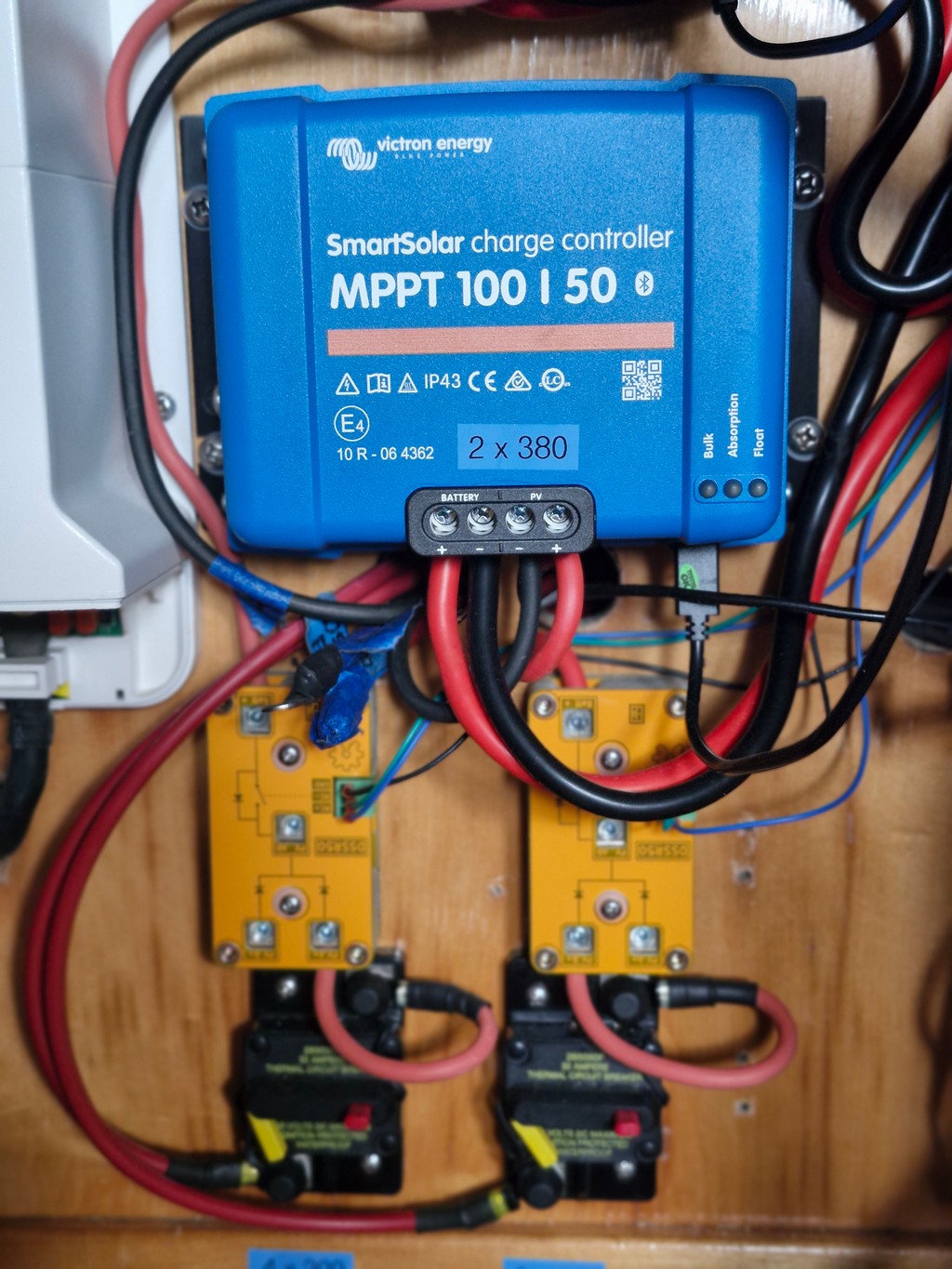
December 2024 Update: Now that we have upgraded our solar system, adding two 380 watt Itoshi solar panels for a total of 1560 watts, we have decommissioned the MorningStar 60 amp controller and purchased two Victron SmartSolar 100 volt/50 amp MPPT controllers. These combined will allow a maximum theoretical solar charging input of 100 Ahrs to our LFP battery; one MPPT for the original 800 watt bank and one for the two new panels with total 760 watt output. That is more than enough to replenish our daily usage of less than 200 Ahrs in less than 3 hours in full sun. We are now using two of the new Electrodacus DSSR50 50 amp relays for control between the panels and MPPTs. They are each capable of handling up to 50 amps. Prices are around $75 US each for a very capable and easily directly controlled unit.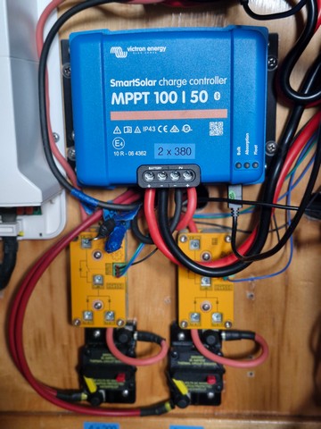
One of two Victron Solar Controllers, 2 DSSR50 Relays,
and 2 Blue Seas Circuit Breakers for Solar SystemIf the panel voltage matched the boat's voltage there would be no need for the expensive solar controllers, and the Electrodacus BMS could handle charge termination without any solar controller (one of the unique features of the Electrodacus design).
- Shore Power Charging: We have a Sterling Power Pro
60 Amp AC charger, which we bought specifically because it has a
"LifePO4" charge profile. Unfortunately, that charge profile is
unrealistic for LFP cells.
The minimum absorb setting is 60 minutes, and cannot be changed. So if it is controlling the charging it will have to be manually shut off when the battery reaches charge termination, as the experts recommend little or no absorb time for LFP batteries.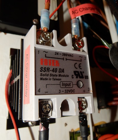
Fotek 40 Amp Solid State Relay for AC ChargerHowever, cutting off charging can be controlled automatically by the BMS using a Fotek 40 amp AC-DC solid state relay (SSR) placed in the AC load wire between shore and the charger. This allows the BMS to control the charge termination of a high voltage event by disconnecting the AC, not the DC wiring. We rarely use shore power for charging, even at the dock, so for now we are just disconnecting the unit from the batteries using a large circuit breaker in the DC wiring.
2026 Update: We have just purchased and installed, in place of the Sterling, one of Victron's IP22 30 A Smart shore chargers. It does its charging using a similar modern algorithm to that of the Victron MPPTs and all parameters are adjustable in "expert mode". Although capable of only 30 A charging, it can be relied on to do its charging work and terminate the charge when done, reliably on a daily basis. The Fotek SSR is still used to provide OVD protection as above.
- Alternator Charging: We have two small 60 amp
externally regulated alternators, one on each engine. Our Wakespeed 500
alternator regulators can be easily configured to handle LiFePO4
charging with both time and tail current regulation and temperature and
voltage sensors. They also have an output throttle
which we set to curtail amps to about 65% of maximum possible, to
make sure we don't stress the alternators too much.
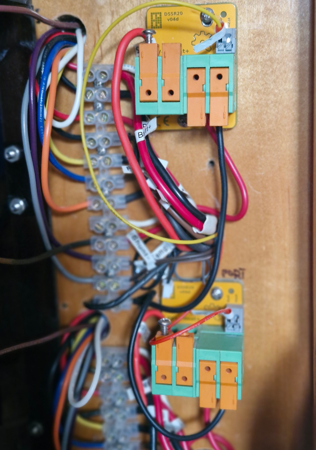
The SBMS0 controls the alternator HVD by disconnecting the ignition/enable wire from the regulator using our DSSR20s. This is preferable to disconnecting the alternator field wire from the regulator because it safely turns off both the alternator and regulator. Since we don't normally use the alternators for charging, we also have a simple on off switch in the ignition wire so charging can be shut down when the engine is running.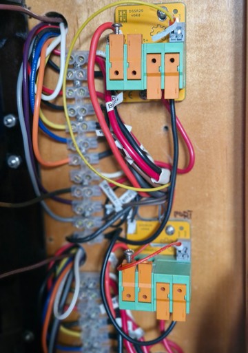
DSSR20 Alternator Regulator Control Relays
with new wiring and screw terminals.Other alternator regulators that are suitable for LFP charging are the Balmar 614 and 618 and the new Zeus regulators.
We have also invested in Balmar Alternator Protection Devices (APDs) that attach to the alternators and absorb any possible high voltage spike in case the alternator gets disconnected suddenly from the battery, while charging. This situation would kill the diodes in the alternator unless there is another battery or APD attached to them. Sterling makes a similar device. Warning: Disconnecting the positive wire while the negative wire remains connected may damage these devices so be careful.
- Switches and Resistors: Most of these SSR relays
and DSSRs are a
little larger than a matchbox and use
about 5 milliamps or less when energized. Because we rarely need to use
the AC charger or alternators, as mentioned above, we also have small on-off switches in
their control circuits from the BMS to turn the relays off when not in
use. These relays, when used with the SBMS0, require a small resistor in the circuit to prevent
excess current getting to the SBMS0 in case of a short.
- Buss Disconnects: As a second line of defense in case of over/under voltage
problems, the SBMS0 also controls two 500-amp high-capacity Blue Seas
7713 relays, set for a higher disconnect voltage. These are placed between the shunts and the two busses in
the main battery cables. They can separately disconnect the
entire charge or
load busses from the battery in case of a problem that wasn't handled by
the other charging source or other load relays. Their HVD/LVD voltages are set
at cell voltage maximum/minimums of 3.75 and 2.50 Vpc. They also
have lighted remote (manual) switches that we mounted at the navigation
station.
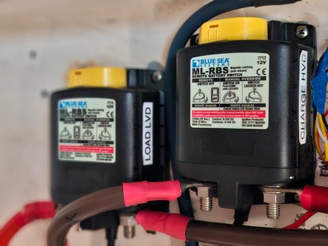
Blue Seas ML-RBS 7713 500 Amp Relays for Charge and Load Busses - Shunts: In order to be able to sense current and
calculate SOC, shunts are required. If one is used for the battery and
one for the charging sources, charge, battery, and load currents can all
be displayed. In the ElectroDacus system, both shunts are mounted on the
positive battery cable. We used quality 200 and 150 amp 100 mV shunts from Reidon
properly sized for our equipment. They are included in the system
diagram above.
- Fuses and Circuit Breakers: Remember that wiring fuses in most cases protect the wiring from overheating and not the equipment. The most important fuse in any LFP system is the one just outside the house battery bank. ABYC recommends this be a Class T fuse within 7" of the battery, as it is one of the very few capable of handling the up to 20,000 amps interrupt current generated if there is a dead short close by down the main battery cabling. Most others could melt and continue carrying the high current which could be disastrous. After that, and at the main busses, use appropriate fusing for the main branch circuits. MRBF fuses are convenient as they connect directly to the buss bar. From there, use reliable fuses or circuit breakers at the source of current, appropriate for the maximum current, but not greater than the Ampacity of the wire.

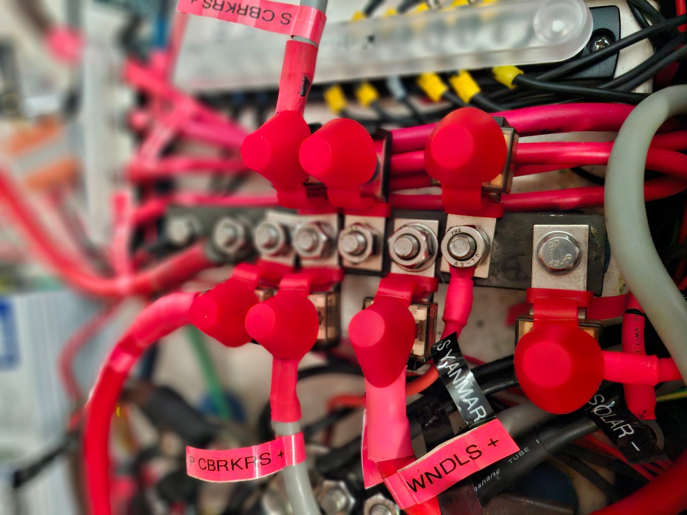 The Load Buss Bar with MRBF Fuses |
Smaller equipment that has their own on-off switches can be powered by convenient Auto 12 Way Auto Blade Fuse Boxes. These are unswitched, but provide blade fuses up to about 30 A for up to 12 circuits. These can be helpful to relieve multiple connections to single switches on marine circuit breaker panels on most boats. They are also useful for providing a home for powering always on emergency equipment like bilge pumps, VHF and navigation lights.
Initial Testing and Balancing: Not everyone will have the time or want to do the initial testing that we did. Originally, we had purchased the original RJ cells with an electrical engineer friend--a total of 24 prismatic 271 Ah cells. Our friend had the proper large load and bench power supply equipment available, and we wanted to fully test that the capacity of the cells we received matched the manufacturer specs. This may be the only way to discover early on a cell lacking capacity or with a high internal resistance.
We started by charging all cells up individually to 3.6 vpc. Then we discharged them individually to 2.8 vpc and graphed the resulting discharge curve and capacity. Finally, we made a graph of the charge curves taking them back up to 3.6 vpc. (see graphs earlier)
After removing the charge, each cell fell back to a rest voltage of about 3.35 vpc. All capacities were within a few amp hours just below 271, since we did not fully charge or discharge them. The charge and discharge curves were similar, but not exactly the same.
Top Balancing: Later we did what is referred to in the literature as a 'top balance'. That is taking all cells in parallel to some voltage above 3.5 vpc--in our case to 3.62 vpc--and letting them continue charging in "absorb" mode to about 5 amp or less tail current. This should get them all balanced to within a few millivolts of each other at charge termination.
Although we did this a second time to less than 1 amp tail current, we did not find it to be very effective at getting the cells closer than about 100 mv apart at charge termination of 3.45 vpc. It probably would have been better to take them only to our charge termination voltage and let them absorb there to an absolute minimum tail current. There are a number of opinions on the internet as to exactly how best to do this.
After that and because our 200 mAmp SBMS0 balancer was not keeping up, we used a rough balancing technique with our 10 amp bench power supply and adjustable load equipment to manually get the cell voltages closer at charge termination. This consists of attaching the equipment to individual or a group of cells to raise or lower their voltage by adding or subtracting milliamps over time.
Regardless of how the cell voltages look at rest, they will always have a much higher delta when the voltage reaches the knee. After a week or so of adding and subtracting mA, cell voltage deltas can be reduced to an acceptable 10-20 mV.
Then the small passive automatic balancer in the SBMS0 was be used to keep them in balance for a short while, despite our not-well-matched cells.
The balancing mechanism on our BMS uses resistors that are latched in during charging, when the cell voltage delta goes above the minimum balancing set point, to suppress charging the highest cell(s). So the lowest cells receive full charge current, while the highest cell(s) receive less.
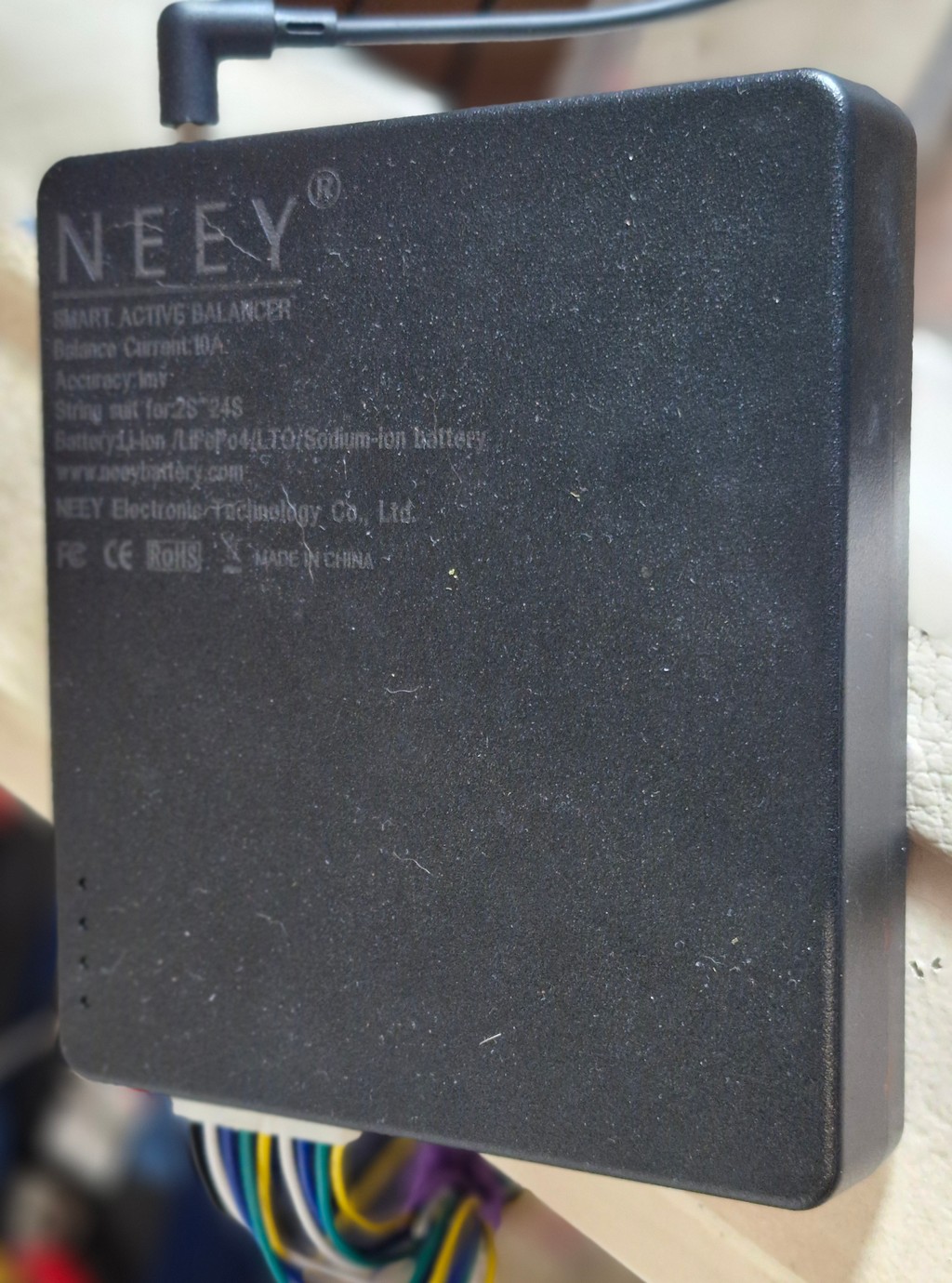 Our 10 Amp NEEY brand Active Balancer As we increased the size of our battery bank, we felt we needed a bigger balancer to keep the cells balanced. |
At a minimum, cell voltages should be resting with less than 10 mV delta and maximum 20-30 mV delta at charge termination. These figures would be entirely adequate for cell balance, but with modern active balancers can be much closer.
2024 Bank Testing Results - Post Mortem: After about 4 years since we originally installed our LFP bank, several of our cells appeared to be significantly out of balance with the rest, so we decided to take them all out of the boat and do some testing. The results showed some of the cells displayed unusual charging curves and some were bulged.
After a retest in mid-2025 of the cells that were not bulged, it appears that the problem might have been how we connected the "sense" wires to the cells when testing, and not necessarily a problem with the cells themselves.
Follow this link to testing results, analysis and what we sent to Lithium on a Boat and the Electrodacus forums to get expert opinions.
https://svsoggypaws.com/files/Battery%20Testing%20Anomalies.pdf
2024 Update: After deciding we wanted to increase the size of our bank, we made the decision to scrap the original 8 RJ cells , and we ordered 12 new EVE 280 Ah cells. The 12 EVE cells came with an information sheet indicating the results of what EVE had found each cell's internal resistance and capacity to be. The capacities were within 2 Ahrs and internal resistances within 1mOhm across all 12 cells.
Our results testing a few of the cells with our new ZKETech EBC-A40L Battery Tester, which is programmable, were the same. The EBC-A40L tester is designed to charge and discharge batteries to a maximum of 5V at a large current (max current it supports is 35A in charging and 40A in discharging). We used this device to also Top Balance all 12 cells to 3.55 vpc before final installation on the boat.
Now, in daily use, the new cells remain closely balanced. Almost a year later we can easily keep the cell voltages at charge termination within 2 mA, just touching up the balance occasionally with the NEEY balancer while the onboard BMS balancer is shut off.
What we have learned since we activated our new bank of 12 cells as a 3P4S (groups of three cells in parallel and four of those groups in series for a 12 V nominal house bank), has helped keep our bank's balance within a very close delta. Basically the 3P4S configuration allows us to need only one BMS which can track each of the four groups of three cells but not each cell individually. So if there is a problem with any one of the cells, it would take a bit longer to recognize compared to a problem with only one cell. But, as mentioned earlier, this would be a very rare situation and takes time to develop. Also, it is easily dealt with by just reducing the bank to one of 2P4S, until a spare cell could be fitted. But any balance problem is just between the four series cell groups, as each parallel 'super cell' acts as one cell with the voltage between them equal by definition. Given our high quality cells and careful installation, this is easily managed. In our case, with the SBMS0 and our NEEY smart balancer, this is only needed very infrequently.
Compared to a 4S3P installation, three separate batteries of four cells each, this is a much better arrangement with fewer installation issues. Three banks would require three BMSs, each with its own bank balancer, three battery boxes, three Class T fuses, and three equal wiring harnesses to a single terminal block. Additionally, keeping the three batteries in balance with each other is not trivial, as each battery must have equal internal resistance and equal wire/termination resistance in order to keep the balance between the three batteries in check. The main advantages of this arrangement are to allow instant disconnect of one battery should there be a problem with one of the three and, if using an internal relay BMS, if there is a BMS fault causing a high or low disconnect of one battery, the other two can absorb the spike.
Basically it is important to thoroughly clean the cell terminals and connecting bars with a good cleaner like vinegar and then alcohol before making the connections. Then torque the connections to 5-6 NM, which is the maximum that EVE recommends for their stud terminals.
- No washers or other connections should be placed between the connection bars and terminals.
- Small female screw terminals set elsewhere in the bars are helpful in connecting sense wiring so as not to interfere with connections to the cell terminals.
- Oversized connection bars of 60 instead of 40 mm2 are required if loads exceed about 200 A.
- For marine applications the bars should be made of flexible tinned copper rather than rigid stainless steel or aluminum in order to handle any excess vibration or swelling during charging.
- And of course, some sort of compression should be fitted on the cell box.
Tools and Equipment
We purchased the following equipment to help us better do the installation and test and maintain the system. Not all this would be required, but on a full time cruising boat, most of it is very helpful should you develop problems in a remote location.
- 30v/10a DC bench power supply with fine adjustment [Amazon Link]
- 20 amp 180 watt adjustable load [Amazon Link]
- EBC-A40L Battery Capacity Tester 5v/40A [Amazon Link]
- NEEY Smart Active Balancer [AliExpress Link]
- UNI-T UT-61E very accurate multimeter with logging [Amazon Link]
- UNI-T UT-210E clamp multimeter [Amazon Link]
- TR-1035+ Internal Resistance Tester [AliExpress Link]
- ENC-30 Digital Torque Wrench [Amazon Link] [AliExpress Link]
- Titan 11477 ratcheting terminal crimper [Amazon Link]
- Klein Katapult 11063W wire stripper [Amazon Link]
- Klein 11074 blade for 16-26 ga (Cat 6) wire [Amazon Link]
- Manual large terminal crimper for #8 to 2/0 terminals
- Fotek AC-DC 40 amp SSR w/ cover and heat sink [Amazon Link] [Heat Sinks]
- Fotek DC-DC 10 amp SSR -3 each with clear plastic covers and heat sinks
- Reidon 200 amp, 150 amp 100 mv shunts- 2 each [Reidon] [Amazon Equivalent]
- Victron BP-100 Battery Protect (100 amp for charge side) [PKYS]
- Victron BP-220 Battery Protect (220 amp for load side) [PKYS]
- Blue Seas ML7700 500 amp relay with remote switches [PKYS]
- ElectroDacus SBMS0 BMS with Wifi [Electrodacus]
- ElectroDacus DSSR50 relays- 2 each [Electrodacus]
- ElectroDacus DSSR20 relays- 2 each [Electrodacus]
- RJ 271 Ah prismatic aluminum case cells- 8 each [RJ Lithium] (our previous cells)
- EVE LF280K V3 prismatic aluminum case cells - 12 each [Docan Power] (our new late 2024 cells)
- Victron SmartSolar 100V/50A MPPT charge controllers- 2 each [Amazon Link]
- Wakespeed 500 alternator regulators- 2 each [Wakespeed Link]
- Victron Blue Smart 12/30 3 IP22 Charger [Amazon Link]
- Blue Sea Systems Class T fuse 400 amp with mounting and cover [Amazon Link fuse] [cover]
- MRBF Fuses of various sizes [Amazon Link]
- Automobile 12 way blade fuse boxes - 2 each [Amazon Link]
- Various wire terminals from 2/0 to 24 ga, marine grade wire 2/0 to 18 ga, heat shrink tubing, Cat 6 cable
- Assortment of 1 watt resistors
- Spares: 2 cells, SBMS0 BMS, 2 ea DSSR20's, various SSRs and fuses.
Note: The links above are designed to take you straight to the
product we bought, so you can see what it looks like and source your own.
Most of this equipment is available from many sources.
Full
disclosure: If you use an Amazon link of ours, we do get a tiny
commission from Amazon.
Lithium Safety and The Insurance Issue
- I suspect that most underwriters are suspicious of Chinese lithium batteries (where almost all of these are made) and BMSs. However, even most 'US' branded 'drop in' lithium batteries use Chinese cells and BMSs.
- LifePO4 technology is different from, and safer than, different chemistry Lithium batteries used in electronic devices like cell phones, and those in cars.
- A year after installation the danger from a cell problem is minimal, but danger from a poor installation or equipment continues. So a cruiser must be very familiar with his/her installation.
- Quality of equipment is a big problem not only with lithium batteries but with all equipment used on a boat. The competition for lithium battery market share is fierce and all sorts of claims are being made by unscrupulous dealers.
- There are several ways to do a lithium installation, including for off grid homes and electric vehicles where a failure is not such a big problem. Not all are suitable for a cruising boat, especially one travelling overseas, where failed equipment or poor installation techniques can spell disaster.
- Not all installers, though 'certified', will be as familiar as you might like with your marine installation. If using an installer, you must be familiar with your boat's electrical system and what will be required for a 'best practices' installation. Make sure the installer is also, and that you both agree with the installation details, especially the equipment.
- Watch the installation very closely and double check the installer's wiring and terminations. This will further familiarize you with the system and hopefully allow you to effectively troubleshoot a problem in the future.
- If you have done the research, know what you are doing, and are willing to do the installation yourself, you can save a considerable amount of money and ensure a proper installation. It is not rocket science. If we can do it properly, so can you.
- A lithium battery installation is not for everyone. If lithium installation challenges are insurmountable, our experience with high quality Gel batteries has convinced us that they are the best lead acid technology for cruisers.
And a couple of thoughts on insurance coverage:
- Insurance coverage is all based on risk. Underwriters want to reduce their risk to match the premium charged. There is a lot of risk insuring US boats including legal challenges, tropical cyclones, inept owners, and now faulty lithium battery installations.
- Insurers are much more careful now than before. Getting any marine insurance has become significantly more difficult. Boat location and age and owner qualifications, experience and claims history all matter now.
- Weather related losses in the Carib and US have been high over the past few years due to huge numbers of boats left in marinas, yards and mooring fields during exceptionally strong hurricanes.
- One possibility for a cruiser installing lithium might be to negotiate with the underwriter exempting losses from a lithium battery problem. If successful, that would present the opportunity do your own work and personally ensure a proper marine installation.
- Finally, a cruiser might delay a lithium installation until leaving for overseas where insurance coverage might be easier to obtain. For us, SE Asia during Covid was a great place and time to do the installation ourselves.
Summary of Safety Features in our Installation
See our "ABYC Compliance Document". We wrote this up to be able to provide a document detailing the parts of our LifePO4 setup that provide the safety features required by ABYC and ISO. So far, our insurer isn't requiring anything like this, but we wanted to get it all documented while it was fresh in our minds.
Have fun learning about this new technology, but remember that not everything you read is true, and the experts don't all agree. The forums, especially, are full of inaccurate opinions. So study carefully, and subscribe as we did, to the preponderance of evidence from the trusted sources below.
A good way to start, as a minimum, after of course reading the entire article above, is to watch some of Will Prouse's YouTube videos, then graduate to some of those from Andy's Off Grid Garage, and finally read the detailed articles at MarineHowTo, NordkynDesign, and FilterGuy's Summary of BMS Functions. Once finished you will be ready to start your LFP project. Links to these resources are below.
YouTube Videos
Will Prowse's DIY Lithium and Solar on YouTube [link]
Andy's Off Grid Garage [link]
Articles
MarineHowTo.com's
LifePO4 on a Boat
This is an excellent beginner's guide that is
continually being updated by expert Rod Collins. Rod is a frequent
contributor to the forums.
NordkynDesign.com's Lithium Pages
This is a much more detailed and technical discussion, divided into
seven segments, recently updated. If your questions can't be answered here,
then there is no answer.
Stan Honey's Thoughts on LifePO4 Batteries on Boats (PDF) Somewhat dated and not updated. [link] or [alt link]
FilterGuy's excellent summary of BMS features is provided in this document on DIY Solar. All beginners should read and understand this before purchasing a BMS.
Beginner's Summary of BMS Functions, Types, and Features
More DIY Solar Forum "Beginner's Resources" [link]
Forums
Boat Electrical Systems Facebook Group - Very well run group with excellent advice specifically for the DIY people on boats.
Lithium batteries on a boat Facebook Group
Electrodacus Google Group (not boat-specific)
ElectroDacus-Specific Information
We have consolidated all of our current knowledge and experience (with contributions from others) for the ElectroDacus SBMS0 BMS on a separate ElectroDacus page. However, we continue to follow many of the links above, especially the forums, for new ideas and updates to the technology and equipment.
[top]
Battery Charging System Philosophy
This is a big subject and it is always interesting to see how others are set up also. Much of how you set up the boat depends on how you plan to use it. If you are dockside most of the time you will want a different system than if you are cruising and away from docks. We are currently cruising, often away from docks and also away from good (expensive) repair facilities.
It has taken me several years to get my new catamaran set up the way I wanted it... with all charging systems wired to the House bank and a trickle charge arrangement for the Start battery. On the catamaran it is a little more complicated because we now have 2 engines and 2 alternators to worry about.
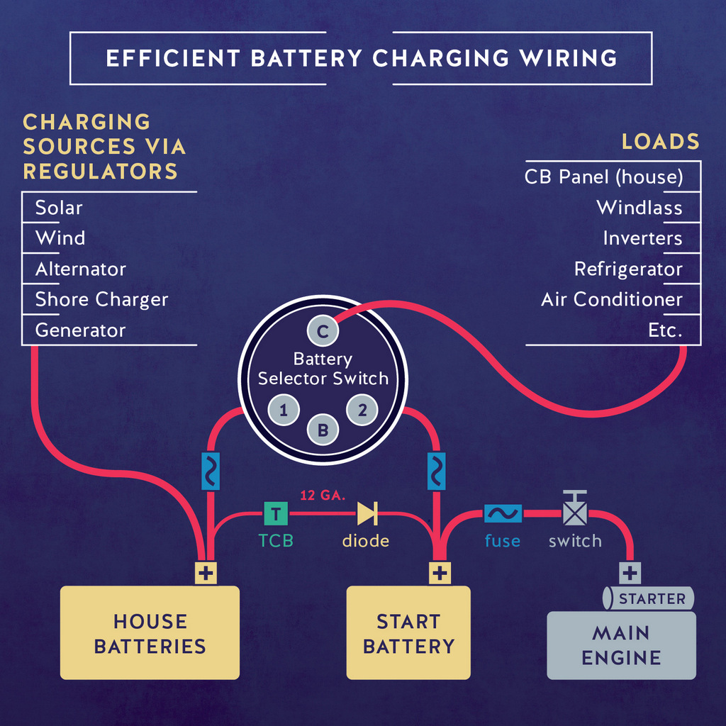
My system keeps the House and Start batteries physically isolated from each other in the normal use/charging situation. It allows multi step charging for the house bank and trickle charging for the start battery.
First, connect all your charging sources (alternator, 120v charger, solar, etc) on one "charge bus" and connect that directly to the house bank.
Run your charging sense and temperature wires to the house bank.
Connect your starting battery direct to the starter. Then connect the house bank to terminal 1 of the battery selector switch and the start battery to terminal 2.
Next connect all your loads to
the common terminal of your battery selector switch. Add cutout switches
and/or fuses as desired in the battery cables within 18" of the batteries, if
you want to comply with ABYC specs.
Finally, connect the positive posts of the house and starting batteries
together with 12 ga wire and a thermal circuit breaker and diode.
See Trickle Charging the Start Battery,
for details, below.
So, if you leave the battery selector switch on 1--the normal situation--the
starting battery starts the engine, and the house bank runs all the loads.
And the two batteries/banks are isolated. If the start battery fails, you
can temporarily place
the switch on Both to combine them for starting.
Also, keep your house batteries away from heat while charging, as it is a killer. If in the engine room, for example, with temps over 115 degrees F you will lose 75% of your cycle life! And if you are using Lead Acid technology for your house bank, don't forget to equalize!
[top]
Start Battery Trickle Charging
At the 1998 SSCA Gam the Four Winds/Everfair owner, Bill Owra, gave what I thought was a very well thought out and much better wiring diagram for a house bank and a starting battery setup. It featured, among other things, hands off trickle charging of the start battery off the house bank, an anti theft switch in the starter/starter battery cable, using the battery selector switch to normally control only battery loads, rather than charging and loading, emergency cross connect for starting and house loads, and routing all charging source cables directly to the house bank so there's no possibility of an alternator or other disconnect problem while charging. It was the best layout I've seen and I've looked at many in the past 20 years of boat ownership.
I thought that the best feature was the automatic trickle charging of the starting battery from the house bank through a short 12 gauge wire with a diode (one way current flow) and thermal circuit breaker.
The idea is that when the house bank is being charged from any charging source the diode will keep the voltage to the starting battery about 1/2 volt below the house bank voltage, and the thermal circuit breaker will break the charging circuit off if the charging amperage get too high.
The starting battery can take up to about 15 amps if it needs it but with this system it normally just takes small float current. I've never seen more than about 2 amps going into my starting battery from the house bank.
This circuit provides a reasonable float charge to keep the starting battery always at 100 percent, just like in your car. A true starting battery with thin, large surface area plates and a high CCA/MCA rating is great for starting your engine and will last as long as your house bank if kept this way.
And it's all automatic with no risk of inadvertently disconnecting the house bank from its alternator charging source. I also keep a couple of spare diodes and thermal circuit breakers aboard just in case.
I used this electrical layout on our CSY, and have just (2018) installed it on our new catamaran. Here are the components required:
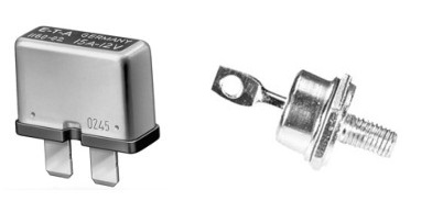
And links to online sources:
60amp 35v Schottky Diode (MBR6035)
And a picture of ours, installed. I just mounted it on a piece of scrap aluminum, near the battery box:
[top]
For the
evolution of our solar system on Soggy Paws the CSY, see this page.
CSY Solar Charging Evolution
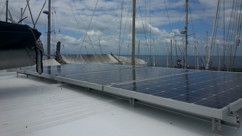
When we bought the catamaran, I sold off the old system that came with the boat and installed 4 new 200 watt 36v panels, and a new Morningstar MPPT solar regulator. Though we really liked the Outback MPPT regulator that we had on the CSY, the Morningstar offered a way to monitor the system via computer connection.
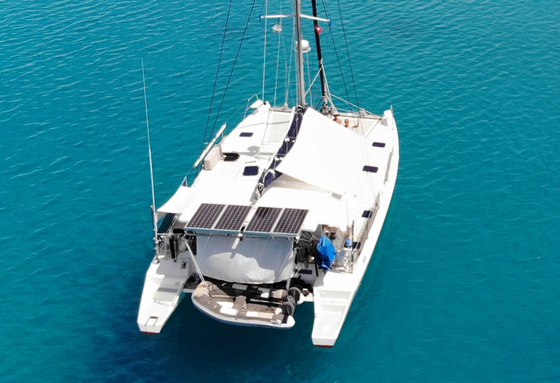 |
Though the catamaran mounting doesn't allow rotation of the panels fore and aft, as we had on the CSY, we made up for it by increasing our solar to 800 watts.
 |
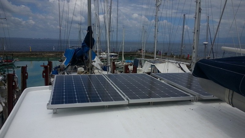 |
As with the CSY system, on a good solar day, we are cranking out the amps, and our batteries are fully charged at mid-day on a sunny day, even if we're wantonly charging computers and stuff. With the excess watts, we can handle several days worth of overcast days before we have to think about charging with other means. Also, in the wintertime, when the solar days are much shorter and the sun angle is not directly overhead even at midday, we have enough power to run the boat at anchor without running any other charging system.
More Upgrades in 2025: In 2025, we added another set of solar panels on our hardtop. 2 380-watt panels. We needed/wanted to split the MPPT charge control across 2 MPPT controllers, so we traded in our Morningstar 60-amp controller for two Victron Smart Solar 100/50 controllers. This required a little bit of software rewrite in our monitoring system, but it wasn't difficult, as Victron has node-red modules available to help.
So our total solar theoretical capacity is now 1560 watts. We have seen peak charging from the 2 sets of panels (combined) at 80 amps around noon. Even with expanded consumption, we are still completing charge by about 1pm every day. (Sunrise and sunset in Malaysia are about 7:30am and pm).
(top)
|
|
|
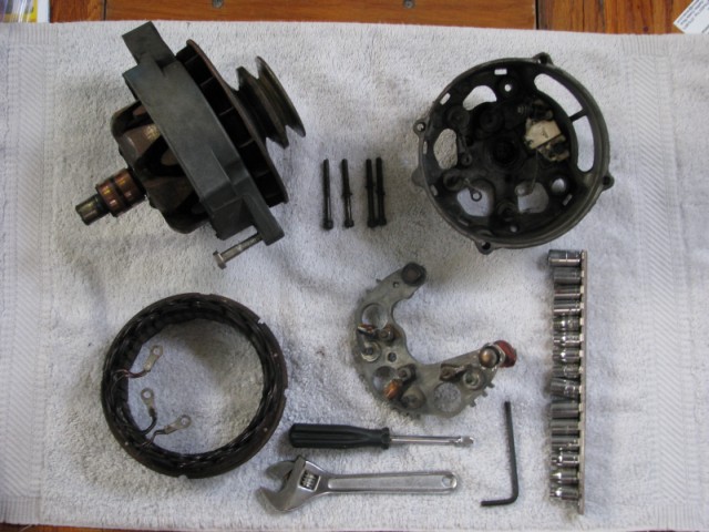
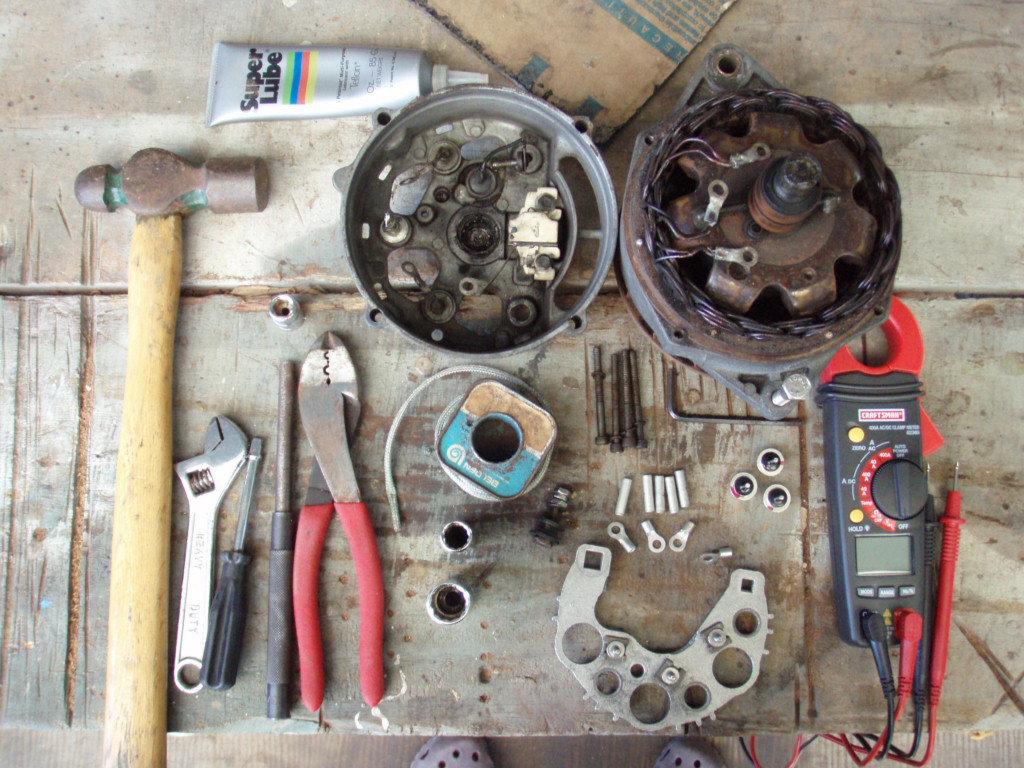
I have taken apart and rebuilt my own alternators ever since
I paid about $100 for a rebuild down in the islands that did not work. The
problem was that the shop installed 30a diodes in my 150a alternator that
needed 50a diodes. Back then I was still trusting third world mechanics with
some of the work on my boat. They are real simple to take apart, test and
replace parts. See
Nigel Calder's Mechanical and Electrical Manual. You certainly don't
need to send them anywhere for repair if you have basic tools, electrical
skills and first time instructions. If you have one of the older Delco,
Balmar or Powerlines, it is fairly simple.
The older Balmar and Powerline alternators look the same, are both based on
Delco alternators and most of the parts are the same including the cases.
Parts are available many places in the US including some Alternator/Starter
parts stores like Royal Battery in Florida and elsewhere. Used parts are
available at auto junk yards and alternator shops everywhere. The small case
alternators are built with capacities up to 150 amps, over that they use
large cases.
(top)
Here is a bit of
interesting info on lightning, its cause, prevention and cure from a
discussion on an SSCA forum:
"Actually, lightning is very well understood in the scientific community.
How it forms and how it reacts is also understood. The University of
Illinois and others have many detailed scientific papers available on the
subject. Exactly where and when lightning will strike is a variable as it is
part of Mother Nature and there is a reason she is called "Mother Nature"
and not "Father Nature."
As to lightning and boats, the issue comes in two parts - 1. Prior to the
strike; and 2. During the strike.
Part 1. concerns how to reduce the probabilities of a lightning strike.
Lightning is a two part event. The ionized "leader" sweeps an area below the
generating cloud and an opposite "leader" sweeps back and forth up from the
surface of the earth. When they connect a pathway is opened and the energy
is discharged. To a boat the ground/earth "leader" is of most interest. As
this "leader" oscillates around it reaches up "x" distance into the
atmosphere. Whenever this leader encounters a vertical object like a tree,
house, telephone/power pole, or the mast of a boat it can reach further up
into the atmosphere and has a better chance of making a "connection." [same
thing as tall men in a bar full of good looking women].
So reducing the "electrical" apparent height of your boat is good. This can
be done with static dissipators such as the Forespar Lightning Master.
(Which is a copy of the static wick principle used on airplanes and
airliners). The sharp small "spikes" of the device "bleeds" off ions as they
build up and electrically reduces your mast height to equal that of the
ocean. However, to do this it must have a "significant" and good ground to
the ocean. That translates to 4 square feet of flat plate copper in contact
with the ocean and 2/0 welding cable between the mast and the plates
submerged in the ocean. A static dissipator will not dissipate if it is not
connected with the ocean.
So the result of part 1. is to electrically make your boat height equal to
the ocean. If you are anchored close to shore or in the close vicinity of
other "unprotected" masts/boats your probability of being hit is
significantly lower than theirs. If you are out in the middle of
no-where/ocean by yourself you are now "even-steven" with the ocean as to
getting a hit.
Part 2. is what can you do to prevent/minimize damage to the boat and its
contents during a strike. Again, the 4 sq ft. of copper joined with
significant sized welding cable to the mast(s) will provide a highly
desirable pathway for the lightning's energy to get directly to its only
objective - earth ground. If the mast(s) are not sufficiently well-grounded
then the lightning energy will try to find an alternate path to the ocean.
If the mast is not available to the lightning, then it will travel down the
shrouds/stays to the bonding system and set up a "field" inside the boat
that will "fry" most electronics and has been known to heat metal thru-hulls
sufficiently enough to melt them out of the hull and you are left with 1.5"
holes for the ocean to enter. Lack of any grounding to the ocean and you can
end up with holes blown through the hull.
Side note: while your boat is floating in the water it is grounded. When you
boat is "on the hard" (out of the water) it is not grounded and any
lightning strike to your boat or to a neighbors boat will fry your
electronics or other fine metal objects or more serious damage. It is
advisable if you are going to leave your boat on the hard, in an area with
probable lightning, to drive a copper or steel grounding stake into the
ground beneath your boat and hook up a significant sized wire from it to
your masts or boat grounding system.
There are many other esoteric factors available to folks wanting to get the
"whole story" such as positive versus negative forms of lightning, high
frequency vs low frequency lightning, etc. but for the boater I think the
primary interest is minimizing damage to the boat, contents, and not curling
the crew's hair. This is done by dealing with the before and during aspects
of protecting/guarding your boat from the energy in lightning.
Exactly where and when a strike will occurs is not determinable - the same
as the actual path of a hurricane or tropical storm is not totally
predicable as there are too many variables in nature for even the powerful
human built computer to input and resolve. So you can only do what you think
is cost-effective to "lower the odds" that you will be the target".
Here is a link with a
good discussion of lightning protection systems and the ABYC rules from a
custom yacht designer dated 2007-09:
www.kastenmarine.com/Lightning.htm
Here's what he says (comparing a 12'
strip to a 1 sf plate):
"The ABYC suggests the use of a grounding strip, rather than a plate. The
ABYC rule states: 'A grounding strip shall have a minimum thickness of 3/ 16
inch (5 mm), and a minimum width of 3/4 inch (19 mm).' A strip approximately
one inch (25 mm) wide and 12 feet long (3.7 m) has nearly six times the
amount of edge area exposed to the water, which will improve the dissipation
of charges. 'The grounding strip, if used, shall extend from a point
directly below the lightning protection mast, toward the aft end of the
boat, where a direct connection can be made to the boat's engine'.
A grounding plate, if used instead, should be solid, rather than the
sintered bronze type often used as radio grounds. The sponge-like structure
of the sintered bronze plates may, in the event of a strike, allow the
instant formation of steam, which could blow the plate apart, resulting in
possible severe damage to the surrounding hull".
An excellent discussion on Marine Grounding
issues (lightning grounds vs radio grounds vs electrical grounds) can be
found in Stan Honey's article on
Marine Grounding Systems.
My copper bar on the CSY was thru bolted to the hull on the port side running from about
the forward main cabin bulkhead aft into the engine room. Two of the 3/8"
bolts are nearly even with the mast so that I could get short runs of 2/0
wire to each from the mast without much bend. The connections need to be
really solid, so I did the mast thru bolted connections while the mast was
out of the boat.
If you Google boat lightning
grounds/protection you will find much more info on this, including this
useful tidbit on Kasten's site:
"The top-most end, or air terminal, should be a sharply pointed spike.
Alternately, a wire 'brush' type terminal can be placed at the masthead,
with the bristles pointed upward. There are several claims that a single
spike is more effective than a brush for dissipating the charge built up by
the boat".
We took both the spike and the bottle brush from the top of the mast on the
CSY when we sold it, and mounted it on our catamaran mast.
My spike is 5/8" aluminum, about 18" long. I threaded the bottom so I could
bolt it through a web in the mast cap. Some pics of the CSY setup
here:
https://www.svsoggypaws.com/CSY/hull.htm#lightninggroundbar
Of all the scary things about cruising and boat ownership, lightning scares
me the most. Not only because of the potential for huge repair expenses, but
also because of the very real threat of loss of life. It is a serious
subject worth careful consideration by anyone using a boat.
[top]
Copyright 2026
WebDesignsInternational