|
CSY |
|


|
Home Page |
||
|
CSY Workshop Home |
||
|
Soggy Paws CSY Home |
||
|
New Cat Workshop Pages |
||
|
Engine |
||
|
Electrical Systems |
||
|
Plumbing
Systems |
||
|
Refrigeration |
||
|
Rig
& Sails |
||
|
Hull |
||
|
Cockpit |
||
|
Deck |
||
|
Interior |
||
|
Steering |
||
|
Electronics |
||
|
Computers |
||
|
Workshop Links |
||
|
Miscellaneous |
||
|
About Us |
||
|
Contact Us |
||
|
About CSY Boats |
||
|
See more 'boat project' discussions by Dave on the CSY Owners Forum |
PLUMBING
Last Updated:
05/14/2023
Fresh Water Tankage
- General Comments
The 400 gallons of fresh water tankage on a stock
CSY 44 Walk-Over is probably more than is needed for just
two people cruising, especially if you add a watermaker. On the Walk-Thru,
we have 165 gallons
in 5 tanks, but if I could chose an ideal water tankage it would be around
250 gallons in 3 tanks. With our capacity, using about 7 gals per day for
both of us, we can go for 20-25 days without a refill. With 250 gals we
could go 35 days, a big difference which would allow us to make any of the
worlds normal long ocean passages without a refill.
 Under
the deck water fills, use a water filter, add some Clorox every now and
then, and taste it for salt contamination. If it tastes good, it has less
than about 500 ppm salt contamination, which is the world health standard
for drinking water.
Under
the deck water fills, use a water filter, add some Clorox every now and
then, and taste it for salt contamination. If it tastes good, it has less
than about 500 ppm salt contamination, which is the world health standard
for drinking water.
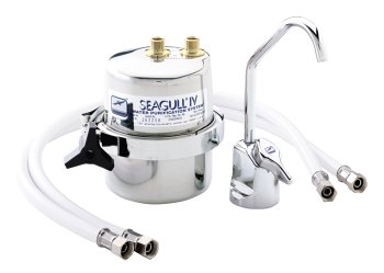
Then use something like a
Sea Gull IV filter for
drinking water bugs. If you are cruising in the Carib or further out you
won't have time to double filter every time you need water, and it is not
necessary. Especially if you are taking on rain water.
Water Catchment
(July 2010 CSYO Post) In response to your
question about water catchment, keep in mind that our boats are different
and the CSY Walk-Over fills are on the upper aft deck while ours are are about two feet
forward of the steps in the lower fore deck. If you look on our website
under Workshop/Deck there are pics of how our deck is set up in this area.
"Tell me more about rain water collection while cruising. What do you do
with it after it enters the boat? Does it get filtered? Do you put directly
into your water tanks?"
To catch water off the entire fore deck we first let it rain for about 10
minutes and maybe do a bit of swabbing down if the deck is dirty. We make
sure that the depression under the mid ships scupper/closed chock is clean.
Then we just stop up the chocks/scuppers with a clean rag, open up the fills
and let the water back up and flow in the fills. The water flows straight
down into standard whole house 30 micron filters under each fill and then
into the tanks. This arrangement is a bit slower than using 1.5" hose all
the way to the tanks but ensures we get no deck dirt/bird poop in the tanks.
After that we use a 20 micron filter before the pressure pump, and a
Sea Gull IV
filter on a separate tap used only for drinking water.
All this works well for the Walkthru. The only problem we have encountered
so far is that often the rain is in a squall and of short duration with lots
of wind. So it is worthwhile being prepared to open the fills quickly. We
have tried various tarp and deck cover arrangements but they don't work well
because of the wind.
If you rig something to stop up the drains in your toe rail on the upper
deck on both side you could do something similar. I believe Steve Silverman
has something for this figured out. Steve are you there?
It looks like your deck has been modified from the original mold with the
depression under the scupper. So with new tanks you could put the fill line
near the top and fill from your forward deck drain like us.
It looks like a workable solution.
Deck Shower and Wash down
We have a have deck shower aft with a quarter
turn shut off valve at at the deck and use a kitchen sprayer for the working
end. We use about 15' of hose so that we can FW wash the dinghy, flush the
outboards and wash down spills on the aft deck and cockpit if needed. I've
been using that now for 10 years.
For pressure SW washdown at the bow for a muddy anchor, etc I use a coiled
50' hose attached in the cockpit to a spigot mounted over the cockpit drain.
That keeps from having to run a long SW hose through the interior of the
boat and minimizes UV damage to the exterior hose. High pressure SW at the
bow is a must for those muddy anchorages. I still see people trying to clean
up the anchor, chain and deck with a bucket and brush. After the SW wash it
is also worthwhile doing a light FW rinse of the anchor windlass and then
putting a Sunbrella cover on it. The cover also keeps most of the SW from
entering the chain locker through the windlass chain hole when you bury the
bow in a seaway.
We use all 3/8" fittings and hose for our shower aft to save water. The
galley sink sprayer nozzle at the end works well with this size hose and
seems to last forever even in the sun. Of course you WO folks can afford to
be more decadent with water than us WT cruisers with more moderate water
capacity.
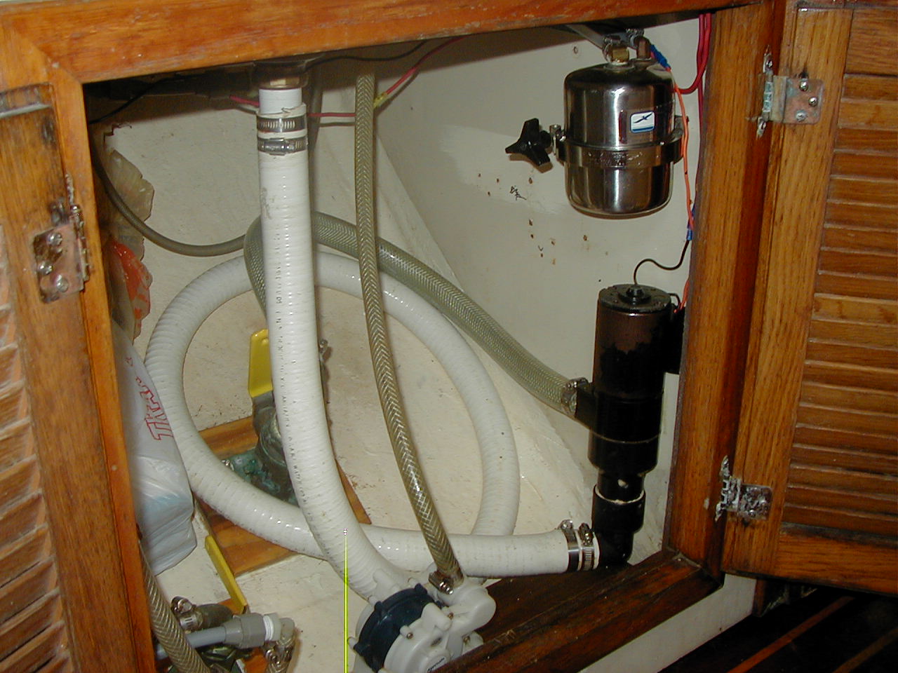
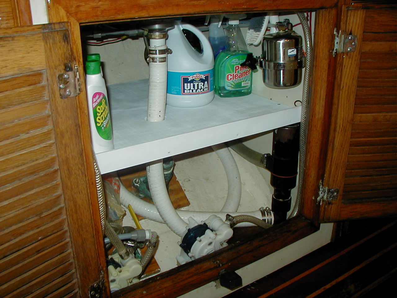
Galley Sink Drain with Macerator
Because ours is a walk thru model of the CSY, the galley sink is outboard on the starboard side. The original configuration had the sink draining straight down into a 1.5" seacock and thru hull. This worked well as long as the boat was on an even heel. But when it was heeled to starboard the salt water came up into the sink because the bottom of the sink was only a couple of inches above the static water line. In rougher weather the salt water would slosh around in the sink and often onto the stove and other galley equipment. The other problem was that the sink would not drain with the boat heeled to starboard.
The fix was designed by Don Wilson of Tackless 2. By simply installing a common macerator pump in the drain line it prevents water from coming up into the sink and allows it to be drained at any time by activating the macerator with a simple Cole Hersee high amp push button switch located in the cabinet face just under the sink. By extending the 1.5" drain line between the sink drain and the macerator pump to about 6' a good amount of washing water can be used before it backs up into the sink and requires draining. This significantly increases the macerator activation interval. This system has worked great now for 8 years.
|
|
|
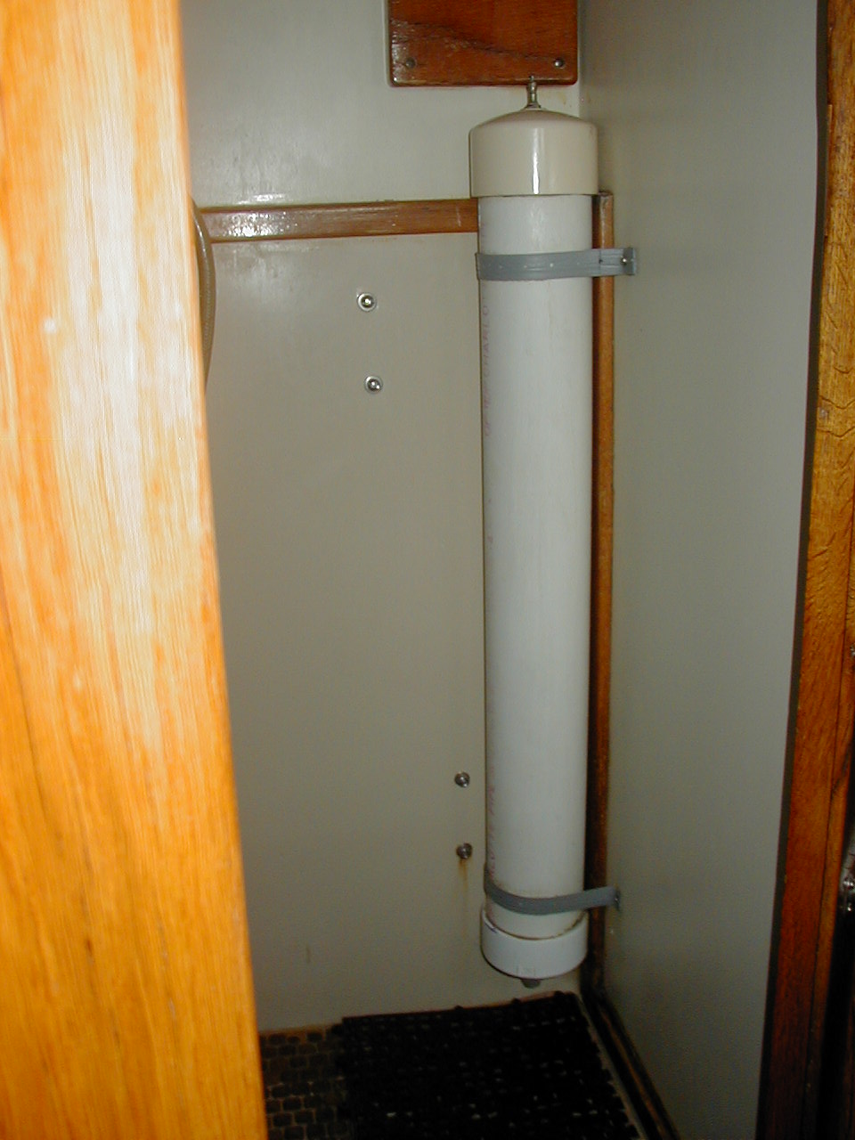
Fresh Water System Accumulator
An accumulator Teed into the pressure fresh water system is a useful piece of equipment because it reduces the pressure pump cycling on and off and therefore the regulator from wearing out prematurely. The pump uses a pressure activated relay to sense the water pressure and turn on the pump when the system needs more pressure and off when it is up to pressure. The relays don't last forever especially if they have to work more often than not. The more frequently they cycle on and off the sooner they will burn out.
After trying several commercially available accumulators, my opinion was that they are too small and too expensive, so I built my own. It is made from a 36" length of 4" sked 40 PVC pipe with caps on each end. The upper cap has a tire inflation valve screw tapped into it so that I can pump more air into it every couple of months. The bottom cap has fittings to attach to my Quest tubing for the pressure fresh water system. It holds a considerable amount of water and air, the air in the top, water in the bottom. When properly charged it greatly reduces the on/off cycling of the fresh water pump. It can be built for less than $20, and is one of those pieces of equipment that that will probably never fail.
|
|
Bottom view, accumulator is on the left |
Engine Driven Water Maker (02 Jan 09-Updates Jan
2012)
Also see our Presentation on Making Our Own Watermaker
Why Engine Driven. Since we carry only 165 gallons of water, and may be at sea for up to 30 days, we decided to install a water maker. I've used a small (6 gallons an hour) 12 volt water maker previously, and it was a real pain running it daily or for hours at a time to keep up with our 6-7 gallon a day usage. Besides that, it needed 17 amps per hour to make its 6 gallons of water.
Some more modern units make about a gallon of water for each amp hour used, but they are very expensive and not easily owner repairable in the field.
Several years ago I saw two home-built units using a commercial HP plunger pump run off the main engine and two of the large membranes producing about 40 gallons an hour. These were each built for around $2K. A similar store-bought unit would cost around $8K and a kit unit about $5K.
So for a savings of up to $6K, and in order to learn more about these systems, I decided to build my own mechanically driven unit. Mine is powered by the main engine since we don't use a generator, but it could also be powered by a generator or an AC motor of about 1.5-2 HP. DC motors aren't available that large, so are not an option. For many reasons I stayed away from using electronic/ automatic control systems, except the electric boost pump, and used only reliable mechanically operated components.
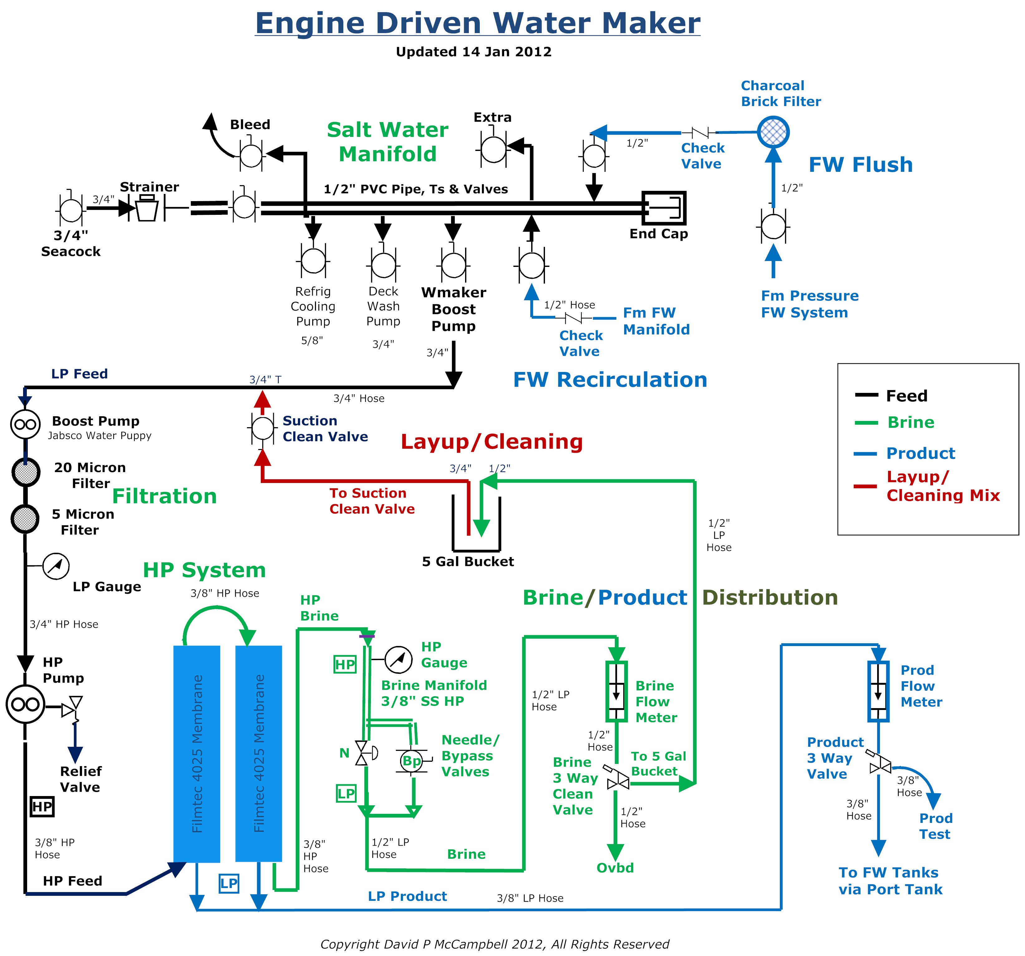
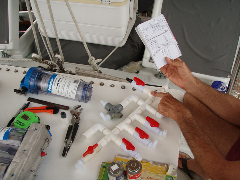
The System Diagram. Above is the diagram of my entire system with all the components shown. (Click on picture to enlarge) There are many ways to lay out a water maker system and different opinions as to what is needed and what is nice to have. I've looked at lots of water maker system diagrams, talked to most of the manufacturers and discussed the fine points with many owners.
While building my system, I stayed away from electronics and automatic systems/sensors because of extra expense, complexity and the high failure rate of electronics in a hot engine room. Also, a lightning strike would certainly kill a system with electronics. So my system is all manually controlled and monitored, since I will be onboard and actively running the system while it is operating.
Equipment Options. Here are my opinions on some of the options available when buying/building a water maker system. These ideas are based on what I have read and discussed with many knowledgeable water maker people.
-
I think both LP and HP pressure gages and brine and product flow meters are necessary for accurate and safe system monitoring. Flow rates and pressures are critical to reliability and long life of the membranes. I bought Dwyer all plastic and SS flow meters and all SS oil filled gages.
-
A good pressure relief valve is necessary for safety when operating the HP portion of the system. I originally used a relief/regulating valve with a bypass feature made for a pressure cleaning gun because it came with my original used pump from a friend. As only the relief valve feature is needed and in order to reduce complexity I have since bought a small brass relief valve and set to pop off pressure to 1000 PSI.
-
Product water distribution and quality can easily be controlled manually with a 3 way valve and portable salinity meter. No need for electronic monitoring here. I can test the product water with my handheld salinity meter or by taste.
-
A boost pump is necessary to maintain positive pressure going into the HP pump no matter where the HP pump is mounted.
-
Fresh water flushing of the system for about 5 minutes is necessary after each use in order to reduce corrosion. This can easily be manually controlled through valves. Again no need for an automatic/electronic system.
-
And finally. cleaning and lay up solutions can be easily mixed and introduced into the system through the use of valves and a 5 gallon bucket. The bucket is also useful for product water waste and testing.
The HP Pump. Cat, Giant, HyPro and several others make good plunger pumps that can be used for a water maker system. I originally installed a two plunger Grainger Teel 2P414D (made by Hypro as a 2230B-P) mainly because it was available used at a good price from a friend. It turned out to be barely adequate for our 40 GPH system.
Because I wanted better flow for good scouring and to ensure full output from the membranes I have since installed a 3 plunger pump (the Hypro 2345B-P, rated at 4.7 GPM but really producing 5 GPM, about $325 new on the internet at www.deindustrial.com June 2008). This also allows me to retain the smaller pump with the same mounting foot print as a backup. (note: as of 2010, deindustrial is out of business, see our Watermaker Links for updated source).
Rather than using a very expensive Stainless Steel or Titanium head HP pump I am using significantly less expensive but entirely suitable bronze head pumps. I am told by several experienced dealers that these should be good for at least 1000 hours of use before the high pressure pulsations with salt water might damage the pump head. At 40 gals an hour that's 40,000 gallons I can make before I can expect the risk of a pump head failure. At 10 gallons a day usage that is about 11 years of use if I use RO water every day. We won't be using RO water every day and there will be at least a couple of months a year when the system will be in layup while we are away from the boat on travel. Given the cost differential, roughly $300 for a bronze head and $1500 for a SS head I am using bronze.
The pump pulley has been sized to allow the pump to run at 1725 RPM when the engine is running at 1400 RPM. The pump will produce its maximum output at that RPM and the engine is comfortable under way or at anchor at 1400 RPM. Since the big pump can produce the full rated 42 GPH through the membranes at about 700 PSI I can run the engine at less RPM if needed and still produce the full rating of product water by simply raising the pressure setting a bit. I have accurately calibrated my engine tachometer and can monitor the engine and HP pump speeds with my handheld electronic tach.
Rather than use an electromagnetic clutch to control the on/off switching of the HP pump I decided to use a manual system with a custom-built SS vertically sliding tray for the pump under the engine front pulley sheave. This decision was based n the following:
-
There is not much room in my engine room for a EM clutch,
-
It is electric and a constantly rotating part, therefore another point of failure
-
AquaMarine, Inc, a vendor of water maker kits, has told their customers that the smaller sizes under about 6 inches are unreliable. Since my engine sheave is 6" I would want a smaller pump sheave size.
It is a relatively simple matter to raise the pump up to attach the belt to the single engine sheave. By pushing lightly down on the pump and locking it in place with wing nuts the belt tension can be set as needed. This setup produces a fool proof, non electric, no-spares-required system.
Operating Calculations.
In water maker literature some flow specs are given in GPH and others in GPM, so convert when necessary by dividing GPH by 60 to get GPM.
The feed input is the sum of the brine and product outputs, since all the water coming in goes to either product or brine. The product output divided by the feed input gives the recovery rate.
With the original smaller HP pump, under operating conditions I planned to run the unit at 1725 RPM, 825 PSI, 2.5 GPM brine output and 40 GPH product output. That assumed I would have 3.2 GPM or 190GPH input from the HP pump to work with. It is rated at 3.0 GPM but really produces 3.2 GPM.
I arrived at these operating parameters by calculating the maximum recovery rate I could make while remaining within Filmtech specifications for long membrane life (max 1000 PSI, each 2540 membrane 21 GPH product flow). The max recovery rate for each 40 inch membrane is 13 percent, so for two membranes in parallel you get 26 percent. A better figure to use without stressing the membranes over the long term is 11 percent each, 22 percent total.
The calculations are as follows.
40 GPH product output divided by 190 GPH feed input (40 GPH product plus 150 GPH brine outputs) gives 20.6 percent recovery, well within specs.
In order to maintain proper scouring/flushing of the membranes at least 2 GPM feed flow is needed, with 4 GPM being much better for long term use. So for the small pump 3.2 GPM (2.5 GPM brine plus .67 GPM product outputs) is OK. For the larger pump, 5 GPM is much better.
Based on
the above, and my own testing at different pressures. I could run the system
with the small pump up to 850 PSI and make 43 GPH at 22.2
percent recovery, but that is
just above the max I've seen recommended for long term use. Filmtech says
the max operating pressure for their membranes is 1000 PSI. 825
PSI is slightly below the recommended max and and well below Filmtech's max,
and it still produces almost as much
fresh water (40 GPH) as running it at 850 PSI. The Jabsco boost pump runs at about 8 PSI
while the system is operating, providing adequate positive pressure against
the HP pump head.
Miscellaneous Info. As of May 2008 the system is up and
operating.
The original HP and LP pumps together pump 3.2 GPM feed under normal operating load. With the larger new pump the feed flow under load is almost 5.0 GPM when pressurized. And it will allow the maximum product flow through the membranes, 42 GPM, 22 percent recovery, at just 700 PSI. This leaves a significant room for pressure increase in order to maintain product flow and good scouring as the membranes degrade over time. So, as of late Sep 08, I am using the larger pump in the system with the smaller pump stored for backup.
The HP pump is engine driven, requiring about 1.5 HP for the smaller pump and just over 2 HP for the larger, and is capable of producing a bit more than 40 gallons per hour from the two 40 inch membranes. At that rate we can run the system once a week for about hour and make up our week's water usage. Running the system once a week with a fresh water flush at the end is a good long term regimen for the membranes. Much longer and there will be problems with biologic contamination.
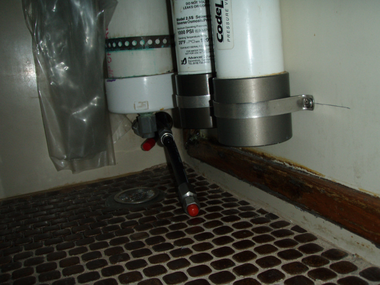
The only electrical part is the 12 volt Jabsco Water Puppy boost pump. I have moved the membranes from the engine room, where the temps in warm weather reach about 120 degrees F, to the aft head where it is much cooler. The Filmtech membrane data sheets indicate the max operating temperature should be no greater than 113 F.
While I was at it, I added a salt water manifold for the deck wash Shurflow Blaster pump, the Marsh 809BR refrigeration cooling water pump, the Jabsco water maker boost pump, water maker cleaning/lay up and fresh water flushing and a fresh water crossover for flushing the manifold and running the refrigeration while on the hard. I also installed a new opening port into the engine room in order to provide some natural ventilation.
The lay up solution (2 tbsp sodium metabisulfite per gallon of water) is sucked out of a 5 gallon bucket through the manifold cleaning system valve as shown on the diagram. The same system is used for the two cleaning solutions. If you start with the system fresh water flushed and full of fresh water, I calculated the system holds about 2.5 gallons of water when all the lines, pumps, membranes and filters are full. Therefore, with the bucket about half full, any mix should be calculated for about 5 gallons.
Regarding cleaning solutions, I've been advised to be fastidious about keeping the membranes clean, away from any petroleum or chlorine products and flush after every use rather than rely on cleaning products to clean the membranes. The membranes can only take a couple of cleanings before they will be permanently damaged and exhibit degraded output.
Additional Info Resources. The original source for much of my inspiration came from another boater. This was originally online here: www.Rutuonline.com. Rutu built his own system using similar components to mine, but with much more in the way of automatic/electronic control systems. His description of how he selected components similar to mine was excellent. However, this site is no longer active. I have recently found another site here: Leo Lichtveld's site.
A second very helpful source is the AquaMarine, Inc website. AquaMarine sells do-it-yourself kits, also using similar components. Both have good detail on equipment choices and installation tips. AquaMarine has a great installation and operating manual, a copy of which might be obtained from another Aquamarine owner.
Also, there are numerous commercial water maker sellers that have websites and handout material of some usefulness. See here for more links to watermaker info and parts suppliers.
Below is a list of the major parts I used and some pictures of the water maker project under construction and as installed on Soggy Paws.
Major parts list:
-Teel 2P414D/Hypro 2230B-P HP Plunger Pump-Bronze Head, 3/4" Shaft, rated at 3 GPM
-or BETTER: Hypro 2345B-P rated at 4.7 GPH at about the same price
source
![]()
(this is what I have now)
-Mount for HP Pump-Custom Stainless Steel by Local Welding Shop
-Boost Pump-Jabsco Water Puppy
18660-121, 12 Volt, rated at 6 GPM, 3/4" Fittings
source
-Pressure Vessels-2 ea, Codeline Model 25M100, 40 inch
source
-Membranes-2 ea, Filmtec SW30-2540 source
-Pressure Relief/Regulating Valve-General Pump ZKSR, adjustable relief
setting
-Water Filter Housings-3 ea, Clear (don't use Pollenex), 3/4" Fittings
-Water Filters-20 Micron Paper, 5 Micron Paper, Charcoal Brick
-Flow Meters-Dwyer, Brine 0-5 GPM, Product 0-60 GPH
-Pressure Gauges-all SS Case/Fitts Oil Filled, HP 0-1400 PSI, LP -30 to +70 PSI
-Needle Regulating Valve-Dragon, SS 1000 PSI (Dragon #10M-053 or McMaster
#4644K33)
-Better option is Grainger's adjustable brass pop off valve
-Bypass Valve-Quarter Turn, SS 1000 PSI
-3 Way Valves with 1/2" Fittings-2 ea, Grey Plastic (SMC)
source
-Hose and Fittings-HP 3/8" hose/fitts, 1/2" SS manifold; LP 3/8", 1/2" and 3/4"
hose/fitts
-Strainer-3/4" Fittings
-Salt Water Manifold-misc 1/2" PVC Pipe, Fittings and Valves
-Mounts-Misc sizes of 3/4" varnished wood to suit, grey plastic pipe hangars
-Salinity Test Meter-Hanna Handheld TDS Meter
-Electronic Tachometer-Neiko Digital Tachometer
|
|
|
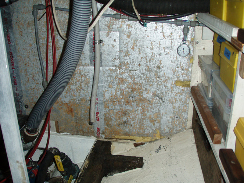 Aft port engine room bulkhead where the salt water manifold and water maker filters will go after removal of a few wires and hoses. |
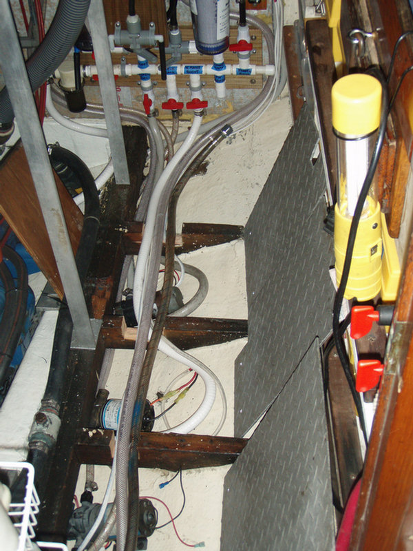 Floor spaces below decking cut into three pieces showing locations of deck wash, water maker and refrigeration salt water pumps. Floors were notched on top to facilitate routing hoses. |
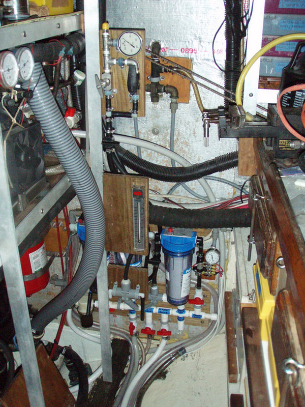 Aft port engine room bulkhead showing manifold, filters, flow meter and HP manifold. The fuel transfer system was later moved to the open space at the top. |
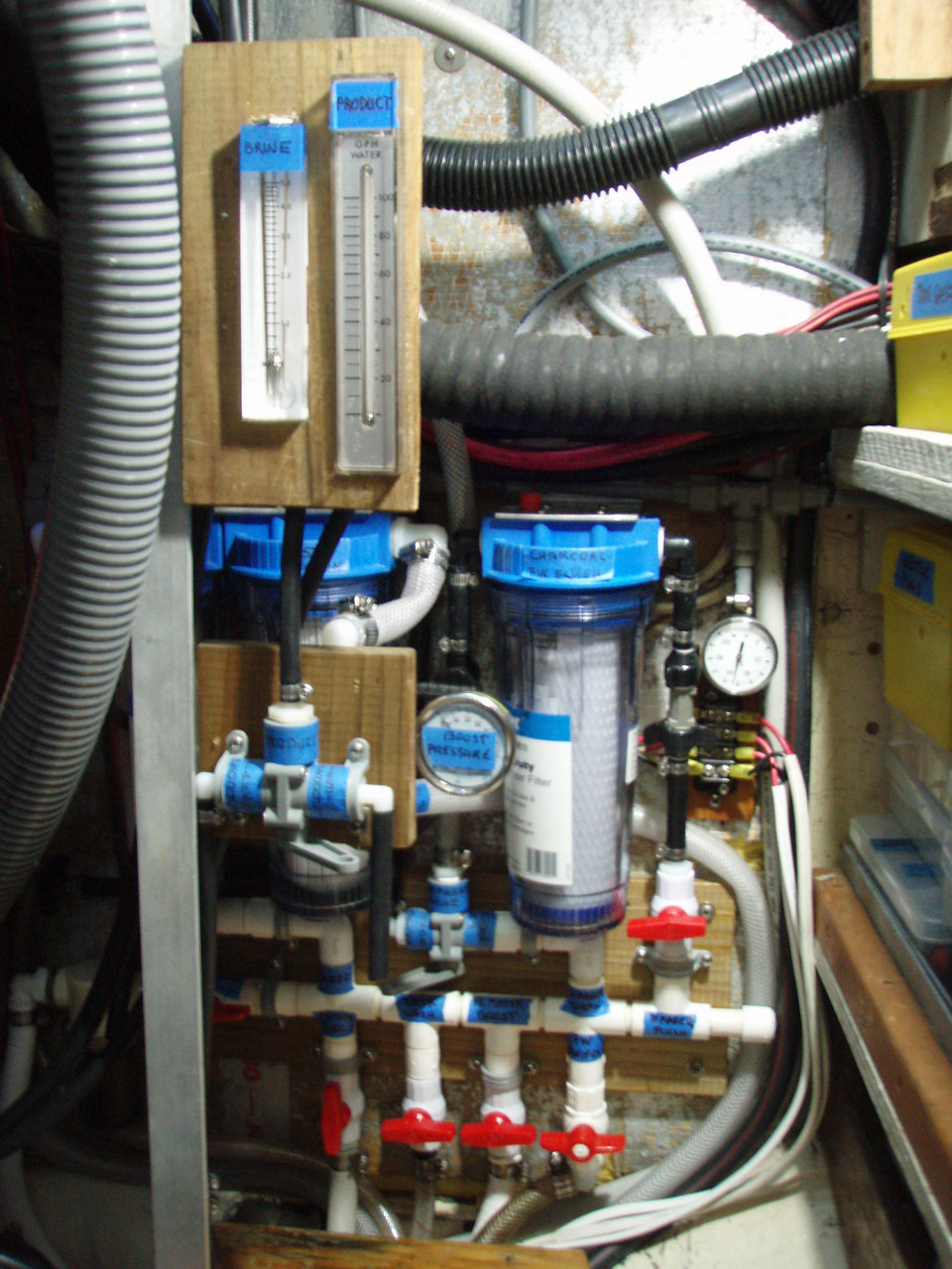 View of lower portion showing flow meters, product 3 way valve, feed LP gage, filters, and SW manifold |
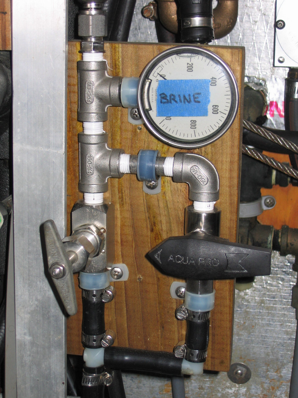 Current view of upper portion showing brine HP manifold, HP gage, needle control valve, and HP bypass valve. Black LP hose and fittings are at bottom. |
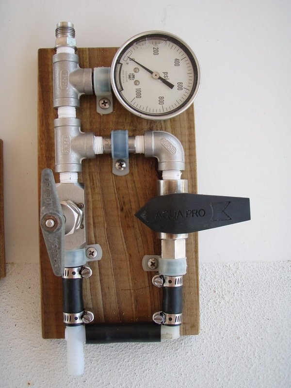 Close up of brine HP manifold showing HP gauge, throttle valve on left and bypass valve on right. |
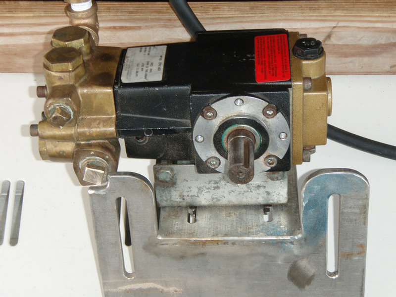 Teel 2P414D two plunger, 3 GPM, bronze head, high pressure pump bolted to its vertically sliding SS mount |
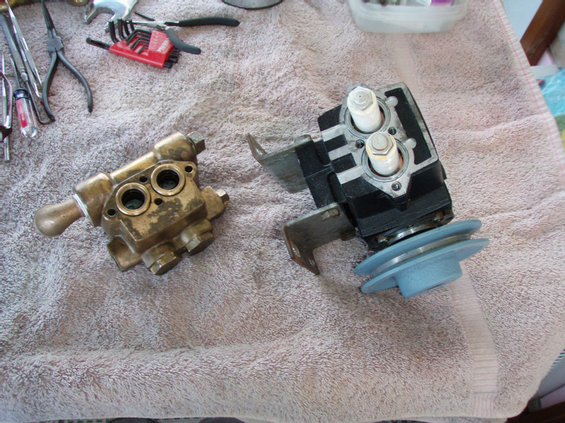 Teel HP pump disassembled into two pieces with pulley in place |
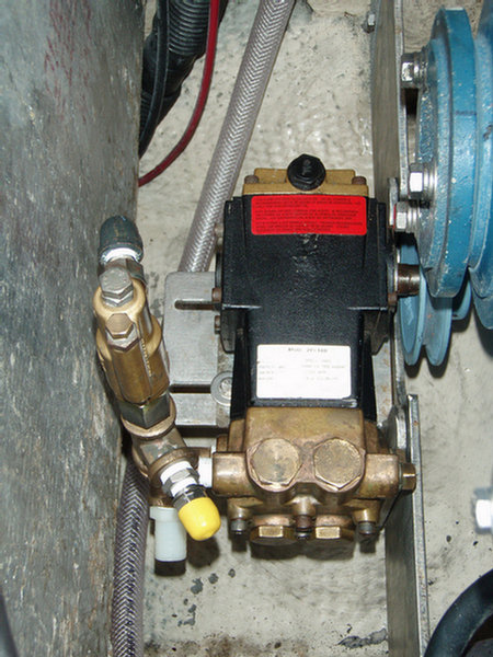 Teel HP pump mounted under the front of the engine. Un- loader valve is on the left. |
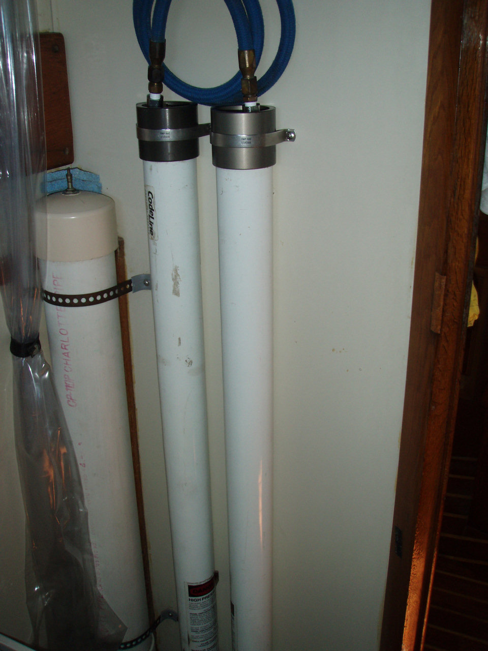 Membrane tubes relocated out of the engine room to the inboard bulkhead of the aft head. PVC FW accumulator is on the left. |
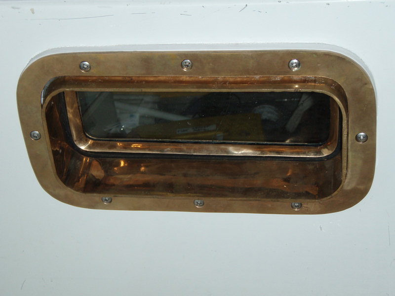 New port into cockpit foot well opens to provide natural ventilation for engine room. |
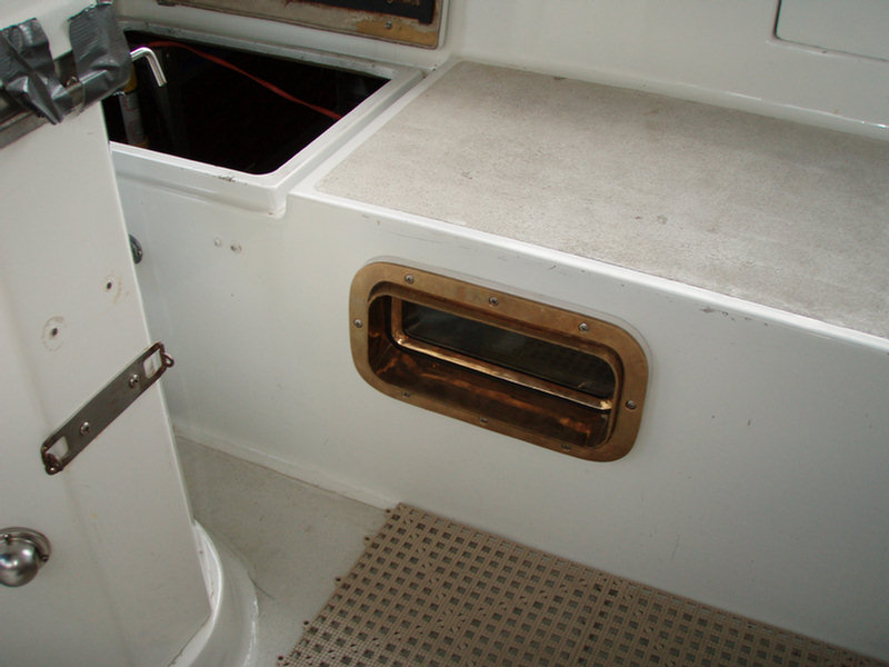 Engine room port location on port side of cockpit foot well. |

Here's
some info
on the fresh water tanks in the Walk Thru model.
There are a total of 5 original tanks. All are fiberglass. The two under the
port and starboard settees gravity drain through brass check valves to the
center tank which is plumbed to a brass manifold mounted on the aft bulkhead
of the bilge sump. Their access plates are all accessible under the settee
seats or floor but are a bear to remove. The two forward tanks are under the
main cabin table on either side of the mast step. They are plumbed
separately to the manifold. Their access plates, if installed, are
inaccessible without performing Sawzall surgery on the floor. If you want to
work with the forward tanks' plumbing/hose connections you will want to
remove the table and mast to gain full access. All the tanks have 5/8 inch
vents going to vent hardware mounted above the rub rails on the topsides.
There are three fills in the deck.
Capacities-
Port settee: 45 gals
Stbd settee: 40 gals
Centerline: 45 gals
Forward: 17 gals each
In order to upgrade the system and make us comfortable using the water for
drinking we have done the following on Soggy Paws:
-
Removed and replaced all the hoses and valves.
-
Made a new PVC manifold with separate 3/4" PVC ball valves for each tank and placed it above the floor under the companionway steps for better access.
-
Installed 1.5" PVC ball valves in place of the brass check valves.
-
Opened and thoroughly cleaned the three big tanks. Replaced the destroyed fiberglass access plates with gasketed aluminum. Removing the access plates will test your tenacity.
-
Included manifold taps for the pressure system, a manual foot pump system and refrigeration cooling water for living aboard during long haul outs.
-
Added a Sea Gull IV filtration system for drinking water.
-
Added household filters just below the deck fill inlets and just after the strainer before the pressure pump.
-
Made a two gallon accumulator tank of 4" PVC and mounted it vertically in the forward starboard corner of the aft head.
-
Changed all the faucets to more modern units with easily replaced valve internals.
-
Replaced all three sinks with larger ones. We like a single large galley sink.
-
Plumbed the galley sink drain through a macerator so it can be drained when heeled.
There's not much more
important while cruising than good drinking water. So we took the time to
try to do a safe, efficient system. It is well worth the effort to spend
some time with your head in the tanks and bilge checking out and cleaning up
your system. Our last project will be to add an engine driven large capacity
water maker before we head out again.
There are original plans and specs for the tanks and the original plumbing
system. They may be on Ed Marill's website. (top)
Two easy projects that gave us much better control of our fresh water system were installing a fresh water manifold under the companionway steps and replacing the check valves with quarter turn ball valves between the side tanks and the centerline tank.
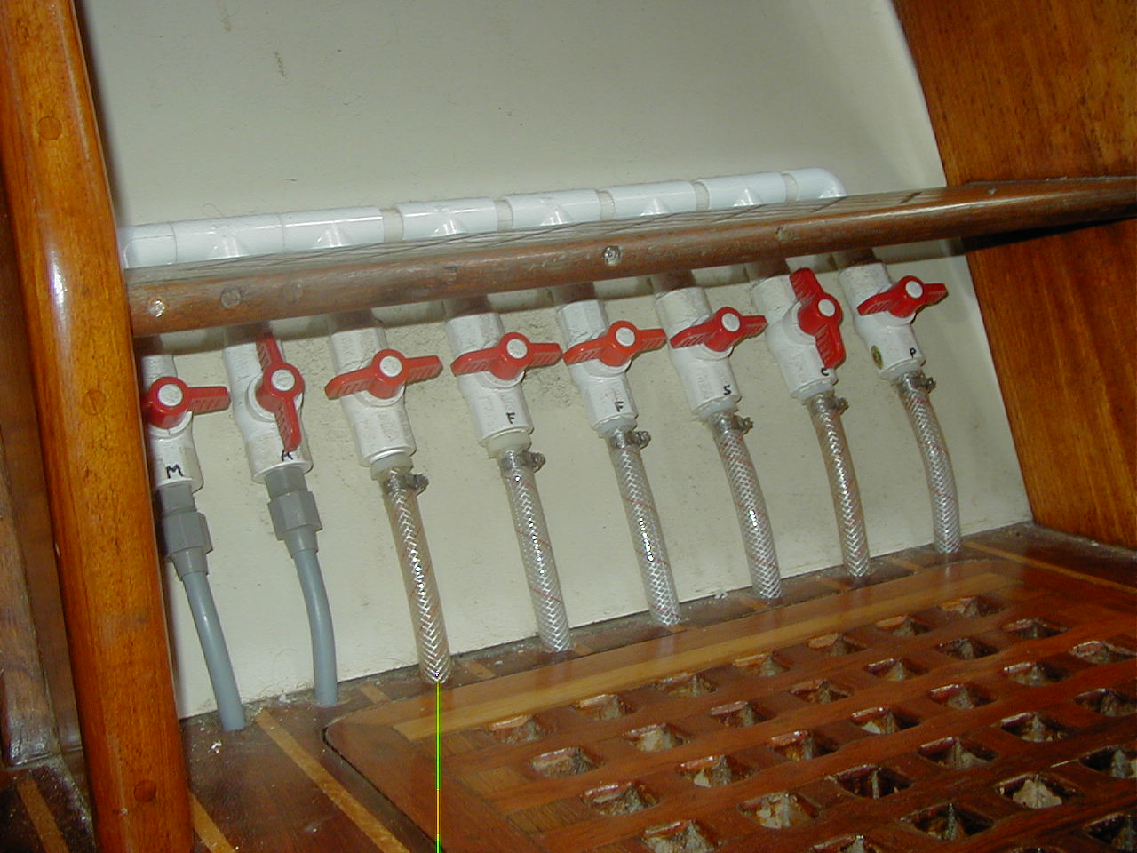
The manifold project involves bringing all the supply hoses from the fresh water tanks out of the bilge through predrilled holes in the floor so you can mount a neat white PVC manifold with 3/4" quarter turn valves under the bottom companionway step. My seven valves are all arranged horizontally under the manifold with the inlets/outlets at the bottom and the manifold running between them at the top. Port to starboard the valves are for:
-
port settee tank
-
centerline tank
-
starboard settee tank
-
port forward 17 gallon tank,
-
starboard forward 17 gallon tank
-
manual supply to galley foot pump
-
automatic supply to pressure pump
-
fresh water circulation to refrigerator system during haul outs
Located here you can easily see which water tanks are on line and which supply system is being used. This system allows you to draw from each tank individually and use either the automatic pump or a manual foot pump in the galley to pressurize the system.
By replacing the bronze check valves in line between the settee tanks and the large centerline tank with 1-1/2" white PVC quarter turn valves you get much better control and isolation capability for all your FW tanks. These valves, suitable hose and PVC pipe and fittings are available at any good hardware store.
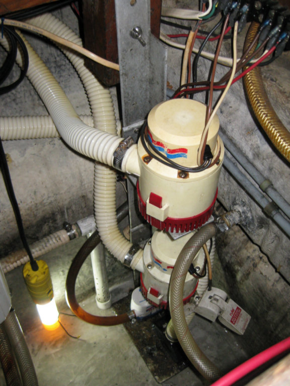
Several years ago I read an article
describing a vertical arrangement for multiple electric bilge pumps in a
deep bilge. There was a small automatic pump at the very bottom which kept
seepage water to a minimum. The next higher pumps were large and for
emergency use. I adopted the arrangement and added the standard large CSY
manual pump and a Y from the engine raw water pump with a custom PVC foot
intake to the mix. I also added a high bilge water alarm sensor just above
the small electric pump. All the electric pumps, the alarm sensor and the
manual pump foot valve are mounted on the standard CSY aluminum angle mount.
The large manual pump is mounted in the port cockpit seat backrest and
empties overboard at a port side waterline thruhull. The small
automatic electric pump empties through a check valve into the forward sink
drain line above the waterline.
The only problem was where to run the discharges for the two large electric
pumps. I really did not want to drill two 1.5" holes in the hull. It has
taken me almost 10 years to figure that out.
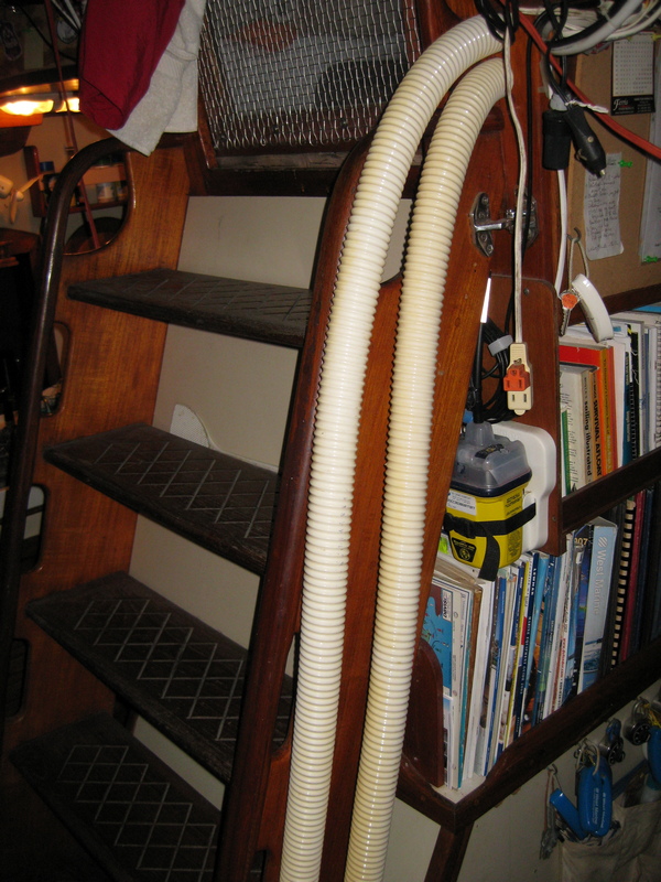
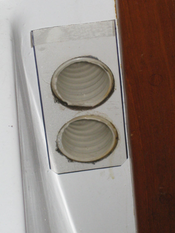
Today I finished running the two 1.5" smooth bore Tigerflex hose discharges
to the cockpit. The two hoses come straight up out of the sump through the
main cabin floor next to the port side of the companionway ladder. Near the
top they turn aft and discharge through the forward cockpit bulkhead about a
foot off the deck. The hose ends are covered by a thin piece of plastic to
keep bugs and such out. The vinyl spiral reinforced Tigerflex MH150 smooth bore hose is much
stronger than the flimsy black plastic bilgeflex hose you find at marine
stores.
This arrangement assumes the two Rule 3700 pumps will be used only for major
emergencies. The advantages are: no additional holes in the hull, a very
straight short run and no back siphon worries. All major issues for large
emergency bilge pumps. Several years ago I changed out the two 1.5" cockpit
drains to 2". So now if we ever have a major flooding inside the boat, we
may get our feet a little wet in the cockpit, but there will be no problem
draining the cockpit in a hurry. And we will know the
big emergency pumps will be operating at full capacity with no back siphon
problems.
I got my Tigerflex hose thru Lewis Marine Supply, but doing a quick Google
search indicates that it should be available in many places.
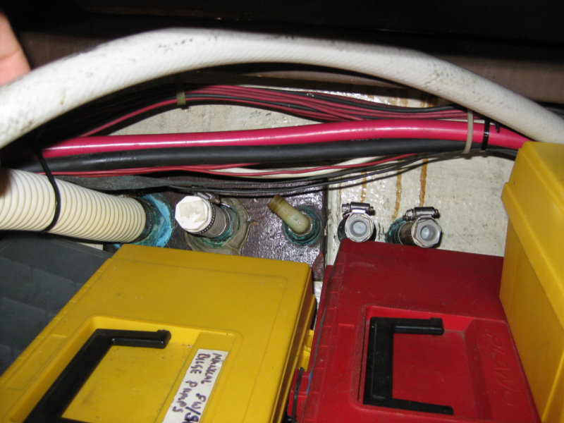
I sealed up 3 small discharge thru hulls in
the side of the boat rather than remove them. What I did was drive an
appropriately sized epoxied wood dowel in from the outside and installed a short
piece of plugged strong hose on the inside. Now there is only one
discharge through the side of the boat, the manual bilge pump as the
refrigeration cooling water discharge has also been plumbed to the cockpit.
What is most important is that I will feel good about the whole thing , even
in the worst weather at sea. I was always worried with the old arrangement
that the bilgeflex hose would chafe through or that I would have a siphon or
thru hull problem. Now I think the system is as
nearly bullet proof as I can make it.
By increasing the diameter of the cockpit
drains to 2" and using bullet proof Tigerflex hose and bronze fittings for
the drains, it seems to me that using the cockpit for the drains, presents
less potential for a problem than running them through the hull at the
waterline. Who knows what might happen in a roll over, but at least I will
not have two more holes in the hull without seacocks.
|
|
|
|
|
|