|
CSY |
|

|
Home Page |
||
|
CSY Workshop Home |
||
|
Soggy Paws CSY Home |
||
|
New Cat Workshop Pages |
||
|
Engine |
||
|
Electrical Systems |
||
|
Plumbing
Systems |
||
|
Refrigeration |
||
|
Rig
& Sails |
||
|
Hull |
||
|
Cockpit |
||
|
Deck |
||
|
Interior |
||
|
Steering |
||
|
Electronics |
||
|
Computers |
||
|
Workshop Links |
||
|
Miscellaneous |
||
|
About Us |
||
|
Contact Us |
||
|
About CSY Boats |
||
|
See more 'boat project' discussions by Dave on the CSY Owners Forum |
ELECTRICAL
Last Updated: 14 Nov 2017
Future Additions:
Freedom 2000 Charger Inverter
Alternator-Regulator Engine Charging
(31 July 09 CSYO Post) Here is a bit of interesting info on lightning, its cause, prevention and cure from a discussion on an SSCA forum at this link:
http://forum.ssca.org/viewtopic.php?f=14&t=8016
"Actually, lightning is very well understood in the scientific community.
How it forms and how it reacts is also understood. The University of
Illinois and others have many detailed scientific papers available on the
subject. Exactly where and when lightning will strike is a variable as it is
part of Mother Nature and there is a reason she is called "Mother Nature"
and not "Father Nature."
As to lightning and boats, the issue comes in two parts - 1. Prior to the
strike; and 2. During the strike.
Part 1. concerns how to reduce the probabilities of a lightning strike.
Lightning is a two part event. The ionized "leader" sweeps an area below the
generating cloud and an opposite "leader" sweeps back and forth up from the
surface of the earth. When they connect a pathway is opened and the energy
is discharged. To a boat the ground/earth "leader" is of most interest. As
this "leader" oscillates around it reaches up "x" distance into the
atmosphere. Whenever this leader encounters a vertical object like a tree,
house, telephone/power pole, or the mast of a boat it can reach further up
into the atmosphere and has a better chance of making a "connection." [same
thing as tall men in a bar full of good looking women].
So reducing the "electrical" apparent height of your boat is good. This can
be done with static dissipators such as the Forespar Lightning Master.
(Which is a copy of the static wick principle used on airplanes and
airliners). The sharp small "spikes" of the device "bleeds" off ions as they
build up and electrically reduces your mast height to equal that of the
ocean. However, to do this it must have a "significant" and good ground to
the ocean. That translates to 4 square feet of flat plate copper in contact
with the ocean and 2/0 welding cable between the mast and the plates
submerged in the ocean. A static dissipator will not dissipate if it is not
connected with the ocean.
So the result of part 1. is to electrically make your boat height equal to
the ocean. If you are anchored close to shore or in the close vicinity of
other "unprotected" masts/boats your probability of being hit is
significantly lower than theirs. If you are out in the middle of
no-where/ocean by yourself you are now "even-steven" with the ocean as to
getting a hit.
Part 2. is what can you do to prevent/minimize damage to the boat and its
contents during a strike. Again, the 4 sq ft. of copper joined with
significant sized welding cable to the mast(s) will provide a highly
desirable pathway for the lightning's energy to get directly to its only
objective - earth ground. If the mast(s) are not sufficiently well-grounded
then the lightning energy will try to find an alternate path to the ocean.
If the mast is not available to the lightning, then it will travel down the
shrouds/stays to the bonding system and set up a "field" inside the boat
that will "fry" most electronics and has been known to heat metal thru-hulls
sufficiently enough to melt them out of the hull and you are left with 1.5"
holes for the ocean to enter. Lack of any grounding to the ocean and you can
end up with holes blown through the hull.
Side note: while your boat is floating in the water it is grounded. When you
boat is "on the hard" (out of the water) it is not grounded and any
lightning strike to your boat or to a neighbors boat will fry your
electronics or other fine metal objects or more serious damage. It is
advisable if you are going to leave your boat on the hard, in an area with
probable lightning, to drive a copper or steel grounding stake into the
ground beneath your boat and hook up a significant sized wire from it to
your masts or boat grounding system.
There are many other esoteric factors available to folks wanting to get the
"whole story" such as positive versus negative forms of lightning, high
frequency vs low frequency lightning, etc. but for the boater I think the
primary interest is minimizing damage to the boat, contents, and not curling
the crew's hair. This is done by dealing with the before and during aspects
of protecting/guarding your boat from the energy in lightning.
Exactly where and when a strike will occurs is not determinable - the same
as the actual path of a hurricane or tropical storm is not totally
predicable as there are too many variables in nature for even the powerful
human built computer to input and resolve. So you can only do what you think
is cost-effective to "lower the odds" that you will be the target".
On Soggy Paws, for grounding, we use a 18"x 5/8" mast top aluminum spike
connected through the mast and heavy copper wire to a 10'x2"x1/4" copper
grounding bar mounted underwater on the hull. The three radios and the tuner
all have quick disconnects, but I still have coax grounds to install. We use
the oven and microwave as faraday cages for computers/electronics that are
out but not permanently installed, and metalized shielding bags for all
stored electrical/electronic equipment. So far no problems; I hope it stays
that way.
(2 Aug 09 CSYO Post) The idea for the copper bar lightning ground came
from the ABYC rules for boat lightning protection. Here is a link with a
good discussion of lightning protection systems and the ABYC rules from a
custom yacht designer dated 2007-09:
www.kastenmarine.com/Lightning.htm
Here's what he says (comparing a 12'
strip to a 1 sf plate):
"The ABYC suggests the use of a grounding strip, rather than a plate. The
ABYC rule states: 'A grounding strip shall have a minimum thickness of 3/ 16
inch (5 mm), and a minimum width of 3/4 inch (19 mm).' A strip approximately
one inch (25 mm) wide and 12 feet long (3.7 m) has nearly six times the
amount of edge area exposed to the water, which will improve the dissipation
of charges. 'The grounding strip, if used, shall extend from a point
directly below the lightning protection mast, toward the aft end of the
boat, where a direct connection can be made to the boat's engine'.
A grounding plate, if used instead, should be solid, rather than the
sintered bronze type often used as radio grounds. The sponge-like structure
of the sintered bronze plates may, in the event of a strike, allow the
instant formation of steam, which could blow the plate apart, resulting in
possible severe damage to the surrounding hull".
Your 4x6" grounding plate is probably a sintered Dynaplate, or similar,
meant for use with an insulated backstay and an automatic antenna tuner to
provide a connection to seawater as a ground plane (not ground) for an HF
radio. As indicated above it should not be used as a lightning ground.
An excellent discussion on Marine Grounding
issues (lightning grounds vs radio grounds vs electrical grounds) can be
found in Stan Honey's article on
Marine Grounding Systems.
My copper bar is thru bolted to the hull on the port side running from about
the forward main cabin bulkhead aft into the engine room. It took me some
time to get the bolt spacing right so I could access them from inside the
boat and not run them into a floor stringer. Two of the 3/8" bolts are
nearly even with the mast so that I could get short runs of 2/0 wire to each
from the mast without much bend. The connections need to be really solid, so
I did the mast thru bolted connections while the mast was out of the boat 12
years ago.
I think the info you often see in lightning literature referring to a plate
is old, and the bar recommendation is more recent. Several universities,
including Florida and Illinois, and others, including NOAA and ABYC, have
done a great deal of recent research on this subject. It is worthwhile
knowing the source and date of info you read, as the recommendations are
changing as new info becomes available. If you Google boat lightning
grounds/protection you will find much more info on this, including this
useful tidbit on Kasten's site:
"The top-most end, or air terminal, should be a sharply pointed spike.
Alternately, a wire 'brush' type terminal can be placed at the masthead,
with the bristles pointed upward. There are several claims that a single
spike is more effective than a brush for dissipating the charge built up by
the boat".
My spike is 5/8" aluminum, about 18" long. I threaded the bottom so I could
bolt it through a web in the mast cap. I also have a short 6" spike I used
when in the Fla Keys running under the 65' bridges. We have the 18" one on
now that we have no bridges to go under.
I'll add a couple of pics to this link on our website when I get time:
http://www.svsoggypaws.com/hull.htm
Of all the scary things about cruising and boat ownership, lightning scares
me the most. Not only because of the potential for huge repair expenses, but
also because of the very real threat of loss of life. It is a serious
subject worth careful consideration by anyone using a boat.
(5 Aug 09 CSYO Post) Re a Dynaplate, it provides a very effective
connection to sea water for your HF radio ground plane. We also have one for
that purpose. No need for lots of copper in the bilge if you have a modern
automatic coupler. Just make sure the Dynaplate is connected up properly and
cleanly with flat copper strips to your coupler.
(6 Oct 09 CSYO Post) The underwater copper bar is 1/4" thick, through
bolted to the hull, with a 1/2" starboard spacers. I use a oring of black
window sealant for the outside seal and 3M Marine Silicone for the inside
under the washer. 3M 5200 would also work, just make sure to chamfer the
holes on the outside so the seal forms an oring around the bolts.
(28 Nov 09 CSYO Post) I don't have any notes on how far apart the
bolts are for the bar. Start by drilling the furthest forward bolt
hole first and then measure back using a total of 6 bolts. Make sure your
holes go into an accessible space beneath your floor. You need the first two
to go through the hull to take wires from the mast. Then you should have at
least one or two all the way aft to ensure the bar stays securely fastened
to the hull. The others can be short screws into the hull. All fasteners
should be bronze. I used ½" Starboard spacers to hold the bar ½" off the
hull so I could clean underneath.
For a really good article on the differences between the lightning ground, the radio ground, and the electrical ground, see Stan Honey's great article on Marine Grounding Systems (pdf file).
(Topica Post 6/1999) Below find some info regarding an electrical casualty we suffered in Trinidad. Hope this will help someone else avoid a rather large repair bill.
While in the Power Boats yard in Trinidad we suffered a voltage spike from shore power that ruined the FETs in the motherboard of our 1993 Heart Interface 2500 watt inverter/charger. Evidently surges like that, and from lightning strikes, are quite common in Trinidad, and in other developing countries also. I had wrongly assumed that the internal circuitry of the unit and my main circuit breaker would have protected it from such an occurrence.
A Heart representative giving a seminar in Trinidad verified that it would not. Evidently some surges are too fast for the internal protection to be effective. At the time I had it wired according to one of the diagrams in their installation manual, so that had the shore power went through the unit in order to make use of the power sharing feature before it fed my 110 v sub breakers.
I was lucky in that there was a local electrical repair shop that is one of the few authorized repair facilities worldwide. After paying up, I was determined not to let this happen again. So after discussing wiring options with the shop manager and the Heart rep mentioned above I used the following arrangement, which might be of help to those of you setting up your own electrical system with an inverter/charger.
The goals were to minimize time of exposure of the inverter/charger to shore power, ensure no possibility of back feeding the inverter from shore power and separate out the loads that should be fed from shore power only. My current 110 v loads consist of a hot water heater, the battery charger and two 110 v wall outlets, totaling four sub circuit breakers. The first two are not suitable for being fed by the inverter and therefore are fed by shore power only. The other two can be fed by either shore power or the inverter. Additional components in the circuit include a 35 amp rotary 2 pole 3 position ('shore/off/gen') switch (available through Defender and others), the 30 amp main breaker, a Link 2000 monitor that also turns on/off the inverter/charger and the Heart 2500 watt inverter/130 amp battery charger. The new circuit goes like this:
- 110 v shore power (positive/black and neutral/white wires) comes in to the main circuit breaker via the boat's 30 amp electrical connector.
- One set of black/white wires from the main breaker feeds the hot water heater and battery charger sub breakers (white goes to a common neutral buss) which are isolated from the other two. These are the shore power only loads.
- Another set of black/white wires from the main breaker feeds the shore side of the rotary switch.
- The 110 v output black/white wires from the inverter feed the gen side of the rotary switch.
- The output black/white wires from the rotary switch feed the two 110 v wall outlets (white goes to the common neutral buss).
- All green ground wires go to a common post/bar and are not switched. I have installed a galvanic isolator in the green wire between the shore power connection and the common green wire post/bar to reduce galvanic corrosion underwater.
When all wired up if you have the rotary switch in the 'shore' position you will feed all four 110 v sub breakers with shore power through the main breaker. The battery charger is on one of these sub breakers which must be turned on to start the charger with the Link 2000. In order to minimize its exposure to shore power the charger is switched on only when we need it. The inverter is isolated from the 110 v system by the rotary switch. With the rotary switch in the 'gen' position shore power is disconnected from the two wall outlets but still feeds the water heater and battery charger sub breakers. The inverter when energized with the Link 2000 feeds the two wall outlets. With the rotary switch in the 'off' position nothing feeds the two wall outlets, but shore power still feeds the water heater and battery charger sub breakers through the main breaker.
Analog meters for AC volts and amps next to the rotary switch allow us to monitor the shore power quality. By only using the battery charger when needed and keeping the rest of the Heart unit out of the shore power circuit we minimize the chance of another problem with questionable shore power sources.
One other component I'd like to have is a 30 amp-capable surge protector to protect the battery charger, microwave and other 110 v equipment when they're on. I haven't found one yet.
From experience, my advice, if you have an inverter/battery charger, is to be sure you understand how it's wired and do all you can to protect it from shore power surges. If you don't it could be a costly lesson.
(Topica Post 6/29/1999) Here's another electrical issue that I came across recently that may be of some use to those of you outfitting your boats for cruising.
We left Florida with an electrical system that I had thoroughly gone through in order to ensure we did not have a problem. I had traced every wire, removing all dead ends, replaced much of the smaller wiring and connections, rewired the battery circuits to provide a house bank and separate dedicated starting battery, replaced and upgraded all the larger cables and end fittings, replaced the batteries and refurbished the box and its shelf, added tie downs for the batteries, added a Link 2000 monitoring system, added a 110 v system, and added a new bank of circuit breakers for our expanded circuits.
I carefully terminated wires and cables with heat shrink and routed the cables so there was minimal chance of a short. The one thing I did not get to was installing high amperage fuses or circuit breakers in the battery cables. Until I had time to install them I figured that I could be careful enough not to cause a short when working around the batteries. Also we normally turn off all loads when we leave the boat.
When we reached Trinidad I was talking with a fellow cruiser who indicated that two boats he personally knew had had fires aboard due to the intense heat buildup from shorted battery cells. A single Trojan T105 for instance can provide over 1000 amps for a short time to a dead short. This is enough to cause a fire even in the large battery cables between the batteries with no other loads turned on-ie your main battery switch turned off.
It was scary enough to cause me to immediately review all my electrical manuals and figure out where I should put in fuses. So far we have added two 300 amp Blue Seas ANL fuses, one each on the positive battery cables about 6 inches from our house and start battery. To protect us from a shorted cell fire we should also have fuses or on/off switches located in the cables between the batteries, but that's a lot of fuses/switches. This looks like another one of those how much is enough protection issues.
In any case we now comply with the ABYC standards for battery cable fusing and I feel much safer. Many cruisers leave home without the basic high amp fuses. As we build more and more into our electrical systems I believe that this is asking for serious trouble. These fuses are cheap insurance against electrical disaster. I would encourage all of you to take a close look at this issue as you prepare your boats for sea. By the way if you're going to do this work yourself purchasing a quality cable terminal crimper is a good investment and makes all this work easy.
|
|
(Topica Post 6/30/1999) Have you been looking for a good way to set up your starting circuit to prevent theft and still provide the capability to instantly start your engine from the cockpit in an emergency? Here's one good way to do it.
First, set up your battery banks so that you have a separate dedicated starting battery, separate, but able to be cross connected to the house bank through a 4 position main battery switch. Route the positive starter cable only to the starter battery such that the engine can only be started through the starter battery. Install a suitable hidden, but easily accessible, on/off switch with a removable key in this starter cable. The $15 Hella on/off switch with red key works fine and is available almost everywhere.
When you leave the boat for a long time take the key with you or hide it aboard. When you're aboard and the engine is not in use at a dock or at anchor, leave the switch off but key in to prevent draining the start battery if you have a short in the starter. When you are sailing with the engine off, leave the key on so the engine can be started quickly in an emergency.
Besides the keyed starter cable switch you should have a suitable ignition circuit breaker below on the panel and a keyed ignition/starter switch in the cockpit, both wired in series. When you are underway sailing, leave the ignition circuit breaker on below and the keyed ignition switch above off. If your below decks switches are both on and you need to do an emergency start, just use the cockpit ignition switch.
When leaving the boat take the two keys with you or hide them aboard. Anyone trying to steal your boat in your absence will have to have two keys, good electrical knowledge and access to your interior. Of course you have your hatch bars in place, so it won't be easy for them to get in. Also, they will have to find your starter cable switch or use jumpers to your starter and figure out the rest of this purposely complicated wiring plan. Given all the trouble you'll put them through they'll hopefully go to your neighbor's boat to do their dirty work. (top)
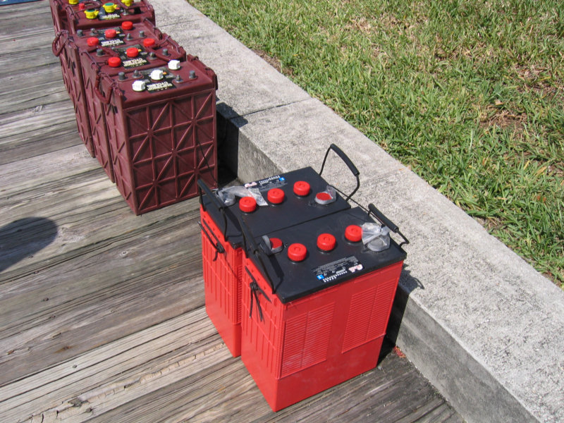
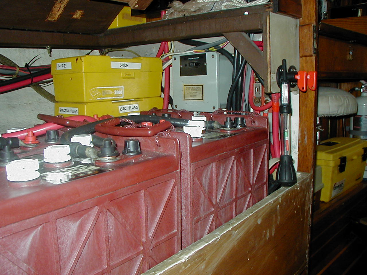
Right - L16 Batteries: Trojan L 16 HC (maroon) and Rolls CH 375 (red).
The Rolls have almost twice the plate thickness and expected cycle life.
(August 07) Originally the boat came with 4 12 volt deep cycle batteries. In 1997 I switched to Trojan T105 golf cart batteries. They are rated at about 220 amp hours at 6 volts each when new and provide more than 400 full deep discharge cycles if properly cared for over their service life. According to Trojan this should give a 3-4 year life span in deep cycling service. I purchased 6 from a dealer in Miami. He mentioned that T105s sell so well because they are well made, provide the most amp hours for the dollar and are one of the few deep cycle batteries that are available worldwide--even in small developing countries. Here is what I wrote in a Topica post then "Trojan T 105 golf cart batteries are an industry standard and very well made for an inexpensive battery, provide the most amp hours for the dollar of any battery and are available worldwide. They can be expected to last 5 years in constant use if they are well maintained and equalized periodically."
Two and a half years later, while still in the Caribbean, my T105's had lost about a third of their capacity and were unable to support the large refrigeration draw; that is their voltage dropped below 12 volts with the refrigerator running, unless I ran the engine. They had been well maintained and equalized every 2-3 months. I purchased another set of 6 locally produced golf cart batteries in Panama which lasted about two years . Upon returning to Florida in late 2002 I researched other options including L16s.
L16 batteries are 6 volt "sweeper" batteries that are 4 inches taller but with the same footprint as "golf cart" batteries. Trojan L16s are about 3 times the cost of T105s ($55 for the T105s vs $170 for the L16 HCs). Their amp hour rating is about 400 amp hours and cycle life is about 1000 cycles. Generally they are more robust than T 105s and have a 5-7 year lifespan according to Trojan. I purchased 6 Trojan L16 HC batteries in late 2002. By 2006 they had lost more than 25 percent of their capacity and were having difficulty supporting the refrigeration load. As we were getting close to leaving on our circumnavigation it was time for more research to try to determine what was causing my batteries to fail prematurely.
I first talked to a friend who had Trojan L16s. He had had problems with his first set also. He had called Trojan and according to a Trojan engineer, he had killed his by not cycling them enough while using a shore power charger while living aboard at a dock. This was not my problem. He also mentioned that the current thinking on the importance of equalizing of lead acid batteries is to do it when the batteries show a loss of charging acceptance or when the specific gravity readings in individual cells vary by more than .03 and not on a periodic (2-3 month) basis. He stated that if you don't equalize your lead acid batteries you will see a significant cycle life loss. A call to the Trojan engineer, Jim Lee, confirmed this and he also recommended monthly specific gravity readings to track any irregularities.
Soon after I read an article with a real eye opener. It indicated that charging batteries installed in the engine room with the engine running was a killer because of the heat generated by the engine. Based on the data in the article and other information I obtained it looked like I could expect over 50 percent cycle life/capacity loss if I left the batteries in the engine room while charging with the engine on. There also was repeated mention of the benefit of using a temperature sensor on the batteries to help the charger regulate the voltage during charging. Bingo, my battery box was in the engine room and I was experiencing repeated premature failures.
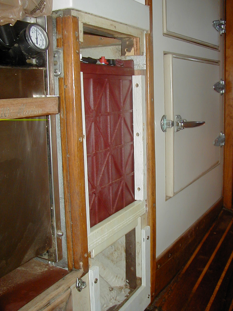
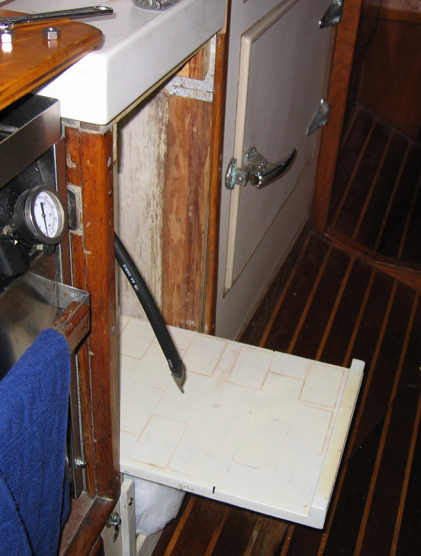
It was time for drastic measures to protect the batteries from heat while charging. There are only a few options for locating the house bank of four L 16 batteries out of the engine room, balanced port and starboard, and within a reasonable distance from the load circuit breaker panel. I had settled on L 16s as being the most efficient from a footprint and cycle life standpoint. I removed the house batteries from the engine room and placed two in a new box under the forward end of the navigation table and two on a pull out shelf in place of the trash bin in the galley. By carefully building the boxes I was able to get them well secured and still provide reasonable access for maintenance. Routing the cables under the galley floor was a trick but solved by persevering and discussion with Steve Silverman. I also made sure both sets of batteries have a big fuse and shut off switch near the batteries and that the cable runs were nearly even from each set to the charging sources.
After moving the boxes I spent a great deal of time researching the three battery types: Gel, AGM and Lead Acid. I found the the Gels and AGMs to be very costly, have relatively short cycle life, and are not made in the L16 case size. For these reasons and, after thorough research on the internet and by phone I purchased 4 new Rolls CH 375 L16 batteries in April 2007 at a very good price with Steve Silverman's help. They have much thicker plates than the Trojans, have a much better cycle life than any of the others and with proper care should last 7-10 years. I talked at some length with Jeremy Surrette at the Canadian factory. The company and their batteries have an outstanding reputation and do have worldwide service. I was looking for batteries that had a reasonable chance of surviving our planned 10 year circumnavigation and the Rolls/Surrette batteries seemed like the only ones that might. See http://www.rollsbattery.com.
12/01/2012 Update: Our Rolls Batteries are still going strong, having been used now for 5+ years, as full-time liveaboards. We have a 'nanopulser' onboard, Watermiser Caps, and I religiously equalize my batteries about every 3 months. I have bought a precision battery tester, which helps me determine how often and for how long I need to equalize.
Topica Post 11/25/08 There is much info on
batteries on the web. You should look carefully at some of that before you
buy. Especially the issues of lead acid vs AGM vs Gell and cycle life.
Believe what independent experts have to say rather than what the
manufacturers write.
You can't do better than Rolls for quality lead acid deep
cycle batteries. Their deep cycle line has the best cycle life of any
battery. Another Rolls option would be to use their equivalent of 6 volt L
16 sweeper batteries, Rolls CH-375s. I now have four of these aboard giving
me about 700 ah capacity. I bought them because I wanted an exceptionally
long life battery.
An alternative to keeping your batteries in the cockpit lockers is to build
in a new box under the companionway steps as several 44 WO owners have done.
This puts the battery weight low, in the center of the boat, and in a
relatively cool place. Heat is a killer for batteries so you certainly don't
want them where they will feel the engine room heat.
For anyone interested in an excellent article on
batteries, here's one of many on the web. The 12 Volt Side of Life, here's
the link:
http://www.ccis.com/home/mnemeth/12volt/12volt.htm
Down in the section titled Selecting Batteries is this little tidbit of
info:
Battery life is reduced at higher temperatures - for every 15 degrees F over
77F, battery life is cut in half. Although he states that RVers don't need
to worry much about this, anyone with batteries in the engine room, where
temps are around 115F, certainly does. I've seen this info before and also
written a bit differently in Nigel Calder books. It explains why the
original 44 WT battery location in the engine room was a battery killer for
me.
|
Four Trojan L16s in original
|
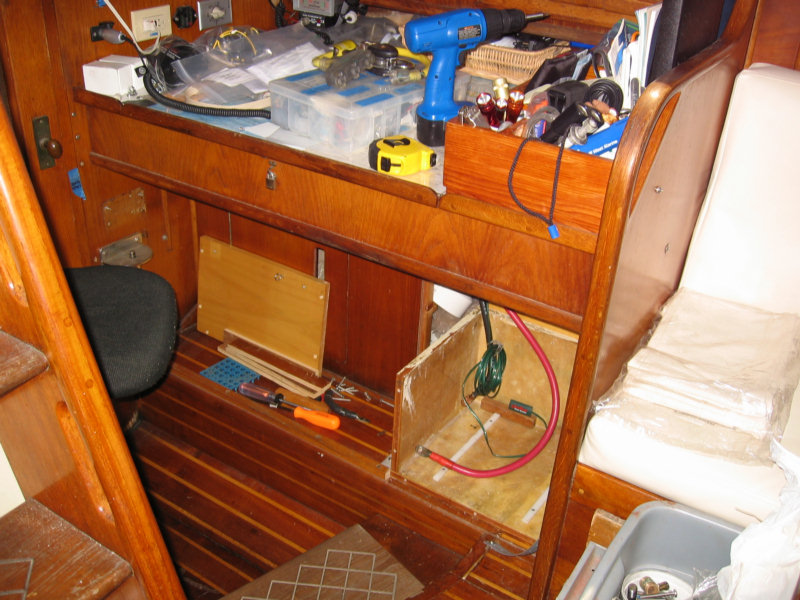
New port battery compartment for
|
|
|
|
2016 Final Rolls Battery Update: We sold Soggy Paws the CSY in April 2016, and the Rolls Batteries were just starting to fail. We got an astounding 9 years out of those batteries, using them 9 months of the year in full cruising mode (and stored with trickle charge for 3 months).
The batteries on our new boat are Sonnenschien Gel Batteries, that are also 10 years old. They are still performing well, so we will stick with them until they need replacement. Next batteries will probably be LifePO4 batteries.
Battery Charging System and Tips
(25 Jan
2010) This is a big subject and it is always interesting to see how
others are set up also. Much of how you set up the boat depends on how you
plan to use it. If you are dockside most of the time you will want a
different system than if you are cruising and away from docks. We are
currently cruising, often away from docks and also away from good
(expensive) repair facilities.
Over the past 12 years my electrical charging/inverter system has evolved so
that it now includes the following equipment:
-440 watts of Seimens solar panels run through an Outback MPPT regulator,
providing up to about 170 amp hours a day with good sun
-a Honda eu2000i portable gas generator, providing 1600 watts continuous
output
-a Powerline 150 amp alternator, with two Balmar backups, run through a
Xantrex regulator
-4 Rolls CH375 (L16) 6 volt lead acid batteries, equalling about 700
amphours at 12 volts
-a common 12 volt 700 cca marine starting battery
-a Xantrex 2000 watt inverter, 100 amp charger
-several small 500 watt inverters, used mainly for the computers
-a Progressive Dynamics 70 watt RV charger
We normally require about 120 ah a day to run the boat. The big refrig
system uses about 80 ah of that. We are basically a solar run boat, but when
there is no sun, we run the Honda and PD70 to charge batteries if we are not
using the engine to move the boat. The PD70 is better than the Xantrex at
charging with the Honda, as it more closely matches the output of the Honda.
The separate charger and inverters back up the Xantrex and vice versa. We
can equalize batts (normally about every 4-6 mos) with solar, alternator,
Honda/PD70 or Xantrex.
I like having backups for all the electrical systems on the boat, as you
never can tell when you are going have a problem. The Progressive Dynamics
and Iota RV chargers make good, relatively inexpensive independent chargers.
We rarely use the Xantrex high output inverter.
A Xantrex problem: it uses pretty simple technology and often it is
relatively easy to repair. You don`t have to send it back to Xantrex for
that. Have any good electonic tech look at it first. When we had a problem
last year in Panama with ours, a local electonic tech, who had never seen
one before, found the problem (burned input relays possibly from running it
with the solar) in about 20 minutes. The relays were readily available.
(Topica Post-Sept 2002) Here are
some general tips on the do's and don'ts of setting up your batteries and
charging systems:
- For alternators capable of charging over about 100 amps, two belts are required to provide adequate power transfer, reduce heat buildup and excessive belt wear. This also provides an installed backup belt in case one breaks. Alternator repair shops have told me that heat from belt wear often causes premature front bearing failure. So keep belts tight.
- Using the main battery switch to switch back and forth as I charged different batteries nearly drove me crazy. Over the long haul and while cruising it's just too hard (at least for my otherwise occupied brain) to remember when to shift. An automatic, fool proof system that you just monitor is far better.
-It is not recommended that you mix in the same bank wet and gel, old and new, different amp hour ratings or case size batteries. Charging unequal battery banks or different type batteries with the same alternator/charger/regulator is also not recommended and will result in overcharging the smaller bank if sensing from the larger bank or vice versa. Each bank needs independent regulation of some sort in order to maximize efficiency and prevent battery damage.
-Float charging wet cell batteries at over about 13.5 volts will require more frequent electrolyte top up and may damage them over the long term. There should be no reason to do this with the modern equipment available.
-Internal alternator regulators will work but are inadequate and best suited to automotive use. They are very inefficient in a deep cycle charging system. They can be removed and blanked off at not much cost so a much more efficient smart external regulator can be used with the alternator.
-If charging efficiency is your goal, high output alternators can cut charging time up to 50 percent over stock alternators and a good smart regulator can improve that by another 50 percent. Stock small alternators should be reserved for backup and wired so they can quickly replace a failed primary alternator. For many reasons your goal while cruising should be to minimize running your main engine to charge your batteries and when you do run it get the charging over quickly.
- Excessive side loads caused by belting heavy equipment on one side of the engine crankshaft pulley can eventually cause problems. This can be offset somewhat by adding a balancing load on the opposite side or positioning the heavier loads on the inside sheaves nearest the engine. When I rebuilt my Perkins 4154, I was able to get the two high output alternator belts on the inside sheaves by reversing the pulley on the shaft and then belted both salt and fresh water pumps on one belt on the third sheave. If either pump fails the engine is out of commission, but not so if the alternator fails. The fourth outer sheave will be used for the high capacity engine driven water maker).
-For many reasons cycling your batteries will produce a 15-20 percent loss as you use amps and then recharge them back into your batteries. If you actually use about 100 amps a day as we do, plan on having to replace that with 115-120 amps from your various charging systems.
-In order to better balance the charge on a large battery bank, the charging leads to all batteries should be about the same length. Do not put both positive and negative leads at one end of the bank or the far batteries will get constantly undercharged due to the voltage drop across the connecting cables. If you have 3 batteries (6 golf carts) or less, cross connect the charging cables by placing the positive lead at one end of the bank and the negative at the other or both on the center battery to minimize the loss. This info came from the Heart Interface rep who gave a seminar in Trinidad when we were there in 2000.
-Maximum safe bulk charging amperage for wet cell batteries is limited to about 25 percent of maximum battery capacity. However, the batteries can't accept max charging amperage for long or the voltage will be driven above their bulk charge voltage limit, about 14.3 volts for wet cells in the tropics, and eventually cause significant damage.
-My original Trojan T105 wet cell house bank when new was rated at about 660 amp hours, therefore my max charging amperage is limited to about 165 amps. Even if I had a bigger or dual alternators, my regulator would build the voltage to 14.3 volts with max amperage over a relatively short period of time and then taper the high amperage off quickly to maintain that set point during the acceptance portion of the charging cycle. Therefore, I think that my 150 amp alternator will be nearly as efficient as a bigger alternator during almost all of this bulk and acceptance stage charging. Trying to charge any quicker or with more amps may damage the batteries and will certainly increase the distilled water usage. Also charging at less than the gassing point, about 14.3 volts in the tropics, with an internal regulator will result in sulfate buildup on the plates and rapid deterioration of the batteries.
-Equalizing wet cell batteries by charging them at an elevated voltage for several hours is a very important preventative maintenance requirement. This procedure will remove residual sulfate on the plates, bring all cells to the same potential, voltage and specific gravity, and mixes up stratified electrolyte and shedded plate material. If you fail to do this on a routine basis you can expect a significantly shorter cycle life with your batteries. The Heart rep said that the latest thinking on this is to equalize when you see the battery capacity being affected not just on a two or three month basis. I recently equalized my two year old batteries after 6 months of light use and raised the at rest PH from 1.250 to 1.280 and voltage from 12.45 to 12.65. Both are significant increases. This will give new life and much needed amp hour capacity as we start our cruise into the western Caribbean. Many battery chargers, alternators, and solar regulators now on the market have this feature. If you have wet cells don't leave home without this capability and a good hydrometer or Misco Precision Battery Tester.
-Distilled water for your wet cell batteries can be obtained from the grocery store, rain water or by running fresh water through your water maker. Even with heavy use in the tropics I only need to add a little water every two months. If you're so inclined Hydro Caps are 90 percent effective at retaining water, can reduce this usage to almost nothing (yearly top off) and also greatly reduce the off gassing. A similar product, Water Misers are about 50 per cent effective and require top off about every four months. Hydro caps are about $10 per cell, Water Misers are about $4 per cell. I bought Water Misers and after 4 months use in the tropics my batteries required only a slight top off.
-High amperage fuses are required safety items close to the positive terminal on the batteries. I used 300 amp Blue Sea fuses. Many cruisers don't have any, but I think that is asking for trouble. They are cost effective insurance against electrical disaster. I also installed emergency cut off switches next to the fuses.
- Get a Misco Precision Battery Tester to take the guesswork out of checking your batteries
(Topica Post 1999, updated August 2007) After 2 years of cruising preps, in the Fall of 1998 we ended up with the following:
-
6 Trojan T 105s (approx 660 amp hour rating)
-
A 850 CCA starting battery
-
A 150 amp Powerline alternator with one 135 amp Balmar and two 55 amp backup alternators
-
A 3 stage smart regulator and backup adjustable regulator
-
A Link 2000 monitor with several backup analog volt/amp gages
-
A Heart Freedom 25 inverter charger with small backups for each.
I had the internal regulators removed from the two 55 amp alternators so they could be used with the external regulators I had. One of these was rewound for low RPM use and was to become a shaft driven alternator for long sailing passages in the future. All the alternators have interchangeable wiring harnesses and similar mounts so they can provide rapid replacement for a failed unit. I resisted mounting one of these spares to the engine, mainly because I did not want to risk damaging it prematurely in case of a system failure, saltwater intrusion or just degrading it from normal wear and tear. My spares are safely stowed in a cool dry secure locker. All charging and load distribution went through the main battery switch. I thought I was ready to go.
Then at the 1998 SSCA Gam the Four Winds/Everfair owner, Bill Owra, gave what I thought was a very well thought out and much better wiring diagram for a house bank and a starting battery setup. It featured, among other things, hands off trickle charging of the start battery off the house bank, an anti theft switch in the starter/starter battery cable, using the battery selector switch to normally control only battery loads, rather than charging and loading, emergency cross connect for starting and house loads, and routing all charging source cables directly to the house bank so there's no possibility of an alternator or other disconnect problem while charging. It was the best layout I've seen and I've looked at many in the past four years.
I thought that the best feature was the automatic trickle charging of the starting battery from the house bank through a short 12 gauge wire with a diode (one way current flow) and thermal circuit breaker. The idea is that when the house bank is being charged from any charging source the diode will keep the voltage to the starting battery about 1/2 volt below the house bank voltage, and the thermal circuit breaker will break the charging circuit off if the charging amperage get too high. The starting battery can take up to about 15 amps if it needs it but with this system it normally just takes small float current. I've never seen more than about 2 amps going into my starting battery from the house bank.
This circuit provides a reasonable float charge to keep the starting battery always at 100 percent, just like in your car. A true starting battery with thin, large surface area plates and a high CCA/MCA rating is great for starting your engine and will last as long as your house bank if kept this way. And it's all automatic with no risk of inadvertently disconnecting the house bank from its alternator charging source. I also keep a couple of spare diodes and thermal circuit breakers aboard just in case. Now in 2007 I'm still using the same system and it has worked flawlessly since installation.
n any case I've been using this electrical layout for the past year and a half, and I'm convinced that it's the perfect system for our boat. A small diagram (source unknown) is here:
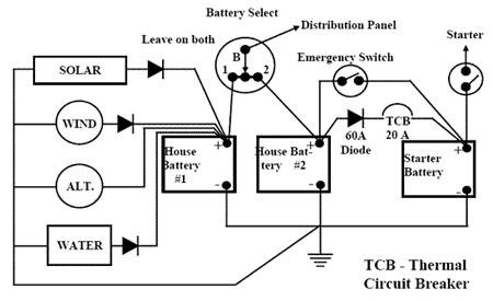
60amp 35v Schottky Diode (MBR6035)
17 Oct 09
Update-
Here's a safe way to charge both your house bank and starting battery, at
the same time with one alternator/regulator. This system keeps them
physically isolated from each other in the normal use/charging situation. It
allows multi step charging for the house bank and trickle charging for the
start battery. It uses a simple, effective and inexpensive system designed
by Bill Owra, formerly of Everfair Enterprises in Punta Gorda, FL. I have
used this system now for 10 years and it does the job well.
Postive connections using appropriate size wire:
First, connect all your charging sources (alternator, 120v charger, solar,
etc) directly to the house bank. Run your charging sense and temperature
wires to the house bank. Connect your starting battery direct to the
starter. Then connect the house bank to terminal 1 of the battery selector
switch and the start battery to terminal 2. Next connect all your loads to
the common terminal of your battery selector switch. Add cutout switches
and/or fuses as desired in the battery cables within 18" of the batteries if
you want to comply with ABYC specs.
Finally, connect the positive posts of the house and starting batteries
together with 12 ga wire and a thermal circuit breaker and diode. The diode
keeps current going toward the start battery and starts trickle charging the
starting battery when the house bank voltage gets .5 volts above the start
battery. The thermal circuit breaker breaks the circuit if there is a
problem (high amperage in the 12 ga wire produces heat). This keeps the
start battery isolated and always fully charged, no cycling. The house bank
does the cycling.
So, if you leave the battery selector switch on 1, the normal situation, the
starting battery starts the engine and the house bank runs all the loads.
And the two batteries/banks are isolated. If the start battery fails, place
the switch on Both to combine them for starting. This system takes the place
of expensive isolators and combiners and costs less than $50. And you never
have to remember to switch your battery charging system from the House bank
to the Start battery.
A shorted/dead battery in either bank is the main reason you do this type of
system to isolate the batteries.
I have watched my system closely when starting my engine and charging the
house bank. A good starting battery (rated about 600 cold cranking amps or
better) will not drop below about 10.5 volts according to Nigel Calder. That
is one of his tests to determine if the start battery is good. My
observations confirm that. As long as your engine starts as it should,
within a few seconds, it will draw only a couple of amps out of the starting
battery. I have never seen more than 2 amps trickle charging back into my
start battery using this system. Normally it is more like .5 amps trickle
charging when charging the house bank.
If you get a shorted cell in the start battery or it dies for some other
reason the TCB will break the circuit and isolate the start battery from the
house bank. That is the reason for the TCB.
The system works well and is every bit as good and safe as a
combiner/isolator. Look carefully though at Bill's diagram and compare it to
my description. I think my layout is better as it eliminates the separate
house banks and streamlines the system a bit.
Also, keep you house batteries away from heat while charging, as it is a
killer. If in the engine room, for example, with temps over 115 degrees F
you will lose 75 pct of your cycle life! And don't forget to equalize.
Solar Charging System with Outback Regulator
In 1998 we had aboard 4 fixed Siemens 55 watt solar panels and a Windbugger wind generator mounted on the port side above them all on an arch aft. In reasonable wind and sun we averaged having to run the engine about 3 times a week for a few hours to keep up with our electrical energy usage (75 amp hours a day for 12 volt DC refrigeration and 25 for everything else while at anchor). If we had one more 75 watt solar panel or a more efficient wind generator or better freezer insulation I think we could have done better.
Upon returning to Florida in 2002 I cut off the wind generator and sold it, added two Siemens 110 watts solar panels and mounted them all so they could rotate fore and aft with nothing above to shade them. These actions made a huge improvement in our ability refrain from running the engine to charge batteries. We spent most of the winter in the Keys on a mooring and rarely had to run the engine.
In 2006 I bought the latest solar regulator technology in an Outback M60. It uses Multi Point Tracking (MPPT) to continually sample the battery and solar array voltage and amperage. Then it reduces the voltage going into the batteries from the solar panels to just a couple tenths of a volt above charge voltage while increasing the amperage to maintain constant wattage from the panels. Amperage gains in the 25 percent range are normal. So them we had four 55 watt panels, two 110 watt panels, all rotatable fore and aft and the Outbacker regulator. With this setup we are capable of producing about 200 amp hours a day with good sun.
In 2011 in Hawaii, with prices of solar panels coming down, and efficiency of the solar cells going up, I replaced the 2 poorest-performing 55-watt panels with 2 140-watt panels. We rearranged the solar system by moving the 2 110-watt panels to the railings on the stern quarter, with a rotating system that will let us fold the panel down when we go to sea.
It took a considerable amount of re-wiring to accomplish this, because the new panels are 24v panels. We had to wire the 12-v panels in series to bring them up to 24v, and then wire these in parallel with the new 24v panels. It took Dave a whole day just to figure it all out on paper before moving things around and rewiring.
Photos of the new arrangement here in our blog
The ability to rotate the big panels fore and aft to follow the sun, is a major item in our solar array. It is amazing to see the amperage jump when we rotate the solar panels in the morning to face the rising sun (from 1-2 amps to 10-15 amps by 9am).
In Cyclone Cyril in 2012, two of our panels got damaged--one of the new 140-watt panels, and one of the older 110-watt panels. The 140-watt panel had been smacked by a another boat's forestay, bending the frame a little bit, and cracking the glass that covers the panel. It looked hardly damaged. So we thought we'd just coat the cracked glass with a clear sealant (something Dave has done before), and all would be good. But when we tested the panel output, we found it was hardly putting out anything. This is when we discovered (with research and talking to an electrical engineer on another boat) that the 24volt panels are wired differently, and damage to just one cell can take out most of the panel. The 12v 110-watter panel, which looked much worse, was actually putting out more amps than the larger lesser-damaged 24v panel.
So we replaced the damaged 140-watt panel when we arrived in Fiji in mid-2011--amazingly we paid LESS for this panel in Fiji than we did for the same exact panel in Hawaii (heavily discounted) the year before.
Finally, by early 2013, the damaged 110v panel corroded to the point where it was putting out next to nothing. We also discovered that the way we had things wired up, that when one of the two side panels was shaded, the other was "dragged down" and not putting out as much as it could be. (Someday I'll have Dave come explain it here in technical terms). So, still being in Fiji in 2013, where they had good Solar World panels available, we replaced the two 110-watt panels with 4 50-watt panels. This allows us to wire each side to 24v individually, so if one side is shaded (as it almost always is in the mornings and late afternoons), the other side is putting out full voltage.
In the middle of summer now, we are cranking out the amps, and our batteries are fully charged at mid-day on a sunny day, even if we're wantonly charging computers and stuff. With the excess amps, we can handle several days worth of overcast days before we have to think about charging with other means. Also, in the wintertime, when the solar days are much shorter and the sun angle is not directly overhead even at midday, we have enough power to run the boat at anchor without running any other charging system.
(top)
Solar Energy System
(Topica Post 12/28/07) Like Ron, I am not a big fan of wind
generators. Having had a
Windbugger for 5 years on a 4 year round the Carib trip, I finally got
rid of it on our return to the US in 2002. I think that they are
expensive, noisy, dangerous, another mechanical piece of equipment to
care for, produce little energy most of the time, and worst of all will
shade the solar panels if you have both aft on an arch (the best place
by far for solar panels).
Read up on them vs total solar in the cruising
websites and ask questions of those that have had both while cruising.
Remember that you will normally be anchored behind islands, trees, buildings
etc rather than 50 miles at sea where the wind generator manufacturers
output charts are based have you believe there is usually 15 knots of wind.
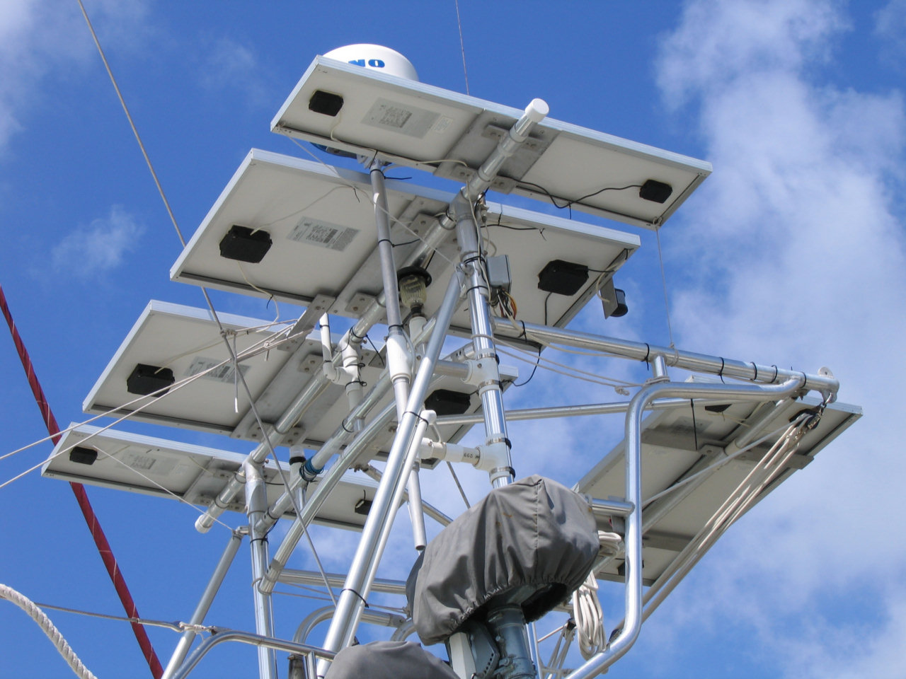
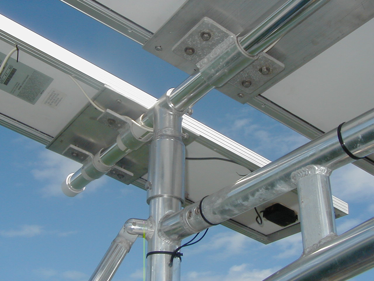
I have my 6 solar panels, 440 watts, mounted aft on my arch so they are
clear of shading and can rotate fore and aft.
 |
 |
 |
 |
Also like Ron I use series wiring and an Outback 60 solar regulator. 440 watts can produce up to about 160 AH a day if rotated 3 times a day. If not aimed at the sun, they produce about 30% less.
That's plenty to run our average 110
AH per day usage while cruising.
Re size of panels: larger panels are a bit more efficient cost wise, but
are harder to secure in heavy winds. I have two Siemens 110 watt and
four Siemens 55 watt. My clamp down system is very secure, and the
panels have been up clamped flat in 75 knots of wind during several Keys
hurricanes with no damage. I would take them off in any more than that.
I recommend you research carefully before making any final decisions as this is an important but very expensive system. You don't want to have to do it over again.
Honda 2000 Generator & Progressive Dynamics Charger (new 2008)
Our solar system keeps up well with all our electrical needs--when the sun shines often enough. But once started cruising near the equator (Panama, Costa Rica, Ecuador) and we stopped moving daily, we found that clouds are more the rule than the exception. And our solar system couldn't always keep up. Rather than run my engine at anchor to charge using the alternator, we decided to purchase a Honda EU2000i gasoline generator.
After 2 years of use, I can say the Honda was a great choice. It is small and compact, gasoline use is measured by the cupfull, it is reliable, and it is a fairly hefty generator, amp-wise, in a small package. Before getting underway, we let it run dry, and then it stores easily on the floor in the aft head.
The challenge with any generator-based charging system is to get as much charge as possible into your batteries in the shortest amount of time, without exceeding the power limitations of the generator. Though I already have a Freedom 20 inverter/charger, I opted to buy a special charger JUST for the Honda, to maximize the charge. The 'load sharing' setup on the Freedom isn't granular enough--it would only permit me to charge at 35 amps and not exceed the load limitation on the Honda 2000.
While looking for the best charger, I read several lengthy discussions on online bulletin boards (SSCA.org) and looked closely at Xantrex, IOTA, and Progressive Dynamics. I ultimately went with the Progressive Dynamics RV Charger, model #9270, with the optional 92201 'Charge Wizard Pendant'. See them here
Though a friend highly recommended the IOTA chargers, they did not offer a 70amp charger, which was JUST what would safely max out the Honda 2000.
Progressive Dynamics Battery Charger
CSY Post 11/20/08 Below are the results of my search
for a good, reasonably priced, battery charger to go with our Honda 2000
generator. It will be the backup for our Xantrex Freedom Marine 2000 when
using shore power but primary (since it can generate 20 more charging amps)
when used with the Honda. The Xantrex can equalize while the Progressive
Dynamics cannot.
Just received the following info from Dave at
Progressive Dynamics.
He had the company engineers test both the 9280 (80 amp) and 9270 (70 amp)
models for maximum/peak input current required during the bulk charging
phase. The 9280 drew 14 amps and the 9270 drew 12 amps, both at 120 volts.
While the Honda puts out a solid 120 volts, less volts in might drive the
input current up. (Volts times amps equals watts).
Input wattage requirements would be as follows:
-PD 9270 120vx12a=1440 watts
-PD 9280 120vx14a=1680 watts
Since the two models are not too different in output, only 10 amps, and the
manual for the Honda 2000 clearly states a maximum continuous output (for
more than 30 mins) must be less than 13.3 amps/1600 watts I will buy the
9270. The Iota DL75 drew 17 amps and their next lower output model has only
55 amps output. All of these units weigh less than 8 pounds, another good
feature.
It took several phone calls to get PD to do all the testing, but now
that it is done I'm glad I forced the issue. We just purchased a PD 9270 for
$217 from an internet RV company (Now available for less on
Amazon.com). Although I would like to have the
conformal coated boards that Iota has, in the interest of maximizing the
Honda's output efficiency, I am not willing to give up 15 amps of charger
output. I'll just keep the PD in a dry place.
After considerable research and discussions with both IOTA
and Progressive Dynamics engineers I bought a PD 9270 70 amp battery charger
from Progressive Dynamics. It has the major advantage of just fitting the AC
output of our Honda 2000 generator. The Honda puts out a max of 13.3 amps AC
continuous and the PD 9270 requires 12 amps AC to produce its full 70 amps
DC for charging. The biggest IOTA that needs less than 13.3 amps AC is their
55 amp model.
I installed it about 10 days ago and we have used it about 8 hours so far.
It produces a solid 70 amps with the internal regulator working as
advertised. It holds the voltage at about 14.2 during accept. I also bought
their small monitor for an extra $10 so I could monitor what stage the
regulator was in and also force the charger into bulk if I wanted.
The unit is small and weighs less than 8 lbs. The case is galvanized steel
so I mounted it in a very dry locker under the nav table. It has a small
muffin fan and a large aluminum heat sink down one side. The DC terminals
will take up to 4 gage wire so you can't mount it too far from the
batteries. I installed a 70 amp Blue Seas circuit breaker in the DC line and
a 15 amp AC breaker. So this is now the primary battery charger with the
Freedom 20 as backup when we are using the Honda.
Mike and I bought our chargers from R and P Carriage off eBay for $220.
They don't seem to still be selling the PD chargers. I was able to talk to the owner
of R and P Carriages about this charger which he said was a RV favorite with
very few problems.
So far we are pleased.
2012 Update: Someone has recently asked us how we like this charger. After 4 years of use, we really like it. Using the bulk mode, we can start charging at 70 amps and the charge only drops off slowly. It halves the time it takes to recharge our batteries using the Honda Generator.
Here's an updated source for the 9270: Progressive Dynamics PD9270
|
|
|
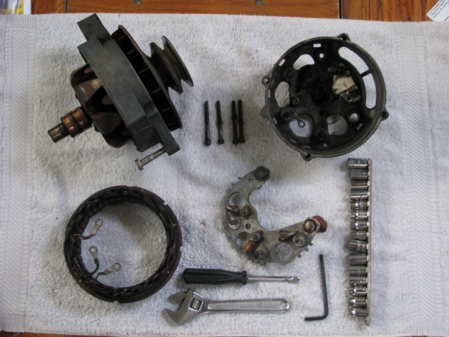
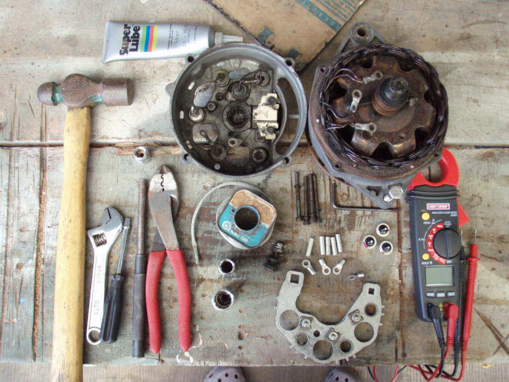
I have taken apart and rebuilt my own alternators ever since
I paid about $100 for a rebuild down in the islands that did not work. The
problem was that the shop installed 30a diodes in my 150a alternator that
needed 50a diodes. Back then I was still trusting third world mechanics with
some of the work on my boat. They are real simple to take apart, test and
replace parts. See
Nigel Calder's Mechanical and Electrical Manual. You certainly don't
need to send them anywhere for repair if you have basic tools, electrical
skills and first time instructions. If you have one of the older Delco,
Balmar or Powerlines, it is fairly simple.
The older Balmars and Powerlines look the same, are both based on Delco
alternators and most of the parts are the same including the cases. Parts
are available many places in the US including some Alternator/Starter parts
stores like Royal Battery in Florida and elsewhere. Used parts are available
at auto junk yards and alternator shops everywhere. The small case
alternators are built with capacities up to 150 amps, over that they use
large cases. If you have a Perkins 4154 with the original alternator, which
is what I started with, the larger alternators with small cases will fit
fine.