|
CSY |
|

|
Home Page |
||
|
CSY Workshop Home |
||
|
Soggy Paws CSY Home |
||
|
New Cat Workshop Pages |
||
|
Engine |
||
|
Electrical Systems |
||
|
Plumbing
Systems |
||
|
Refrigeration |
||
|
Rig
& Sails |
||
|
Hull |
||
|
Cockpit |
||
|
Deck |
||
|
Interior |
||
|
Steering |
||
|
Electronics |
||
|
Computers |
||
|
Workshop Links |
||
|
Miscellaneous |
||
|
About Us |
||
|
Contact Us |
||
|
About CSY Boats |
||
|
See more 'boat project' discussions by Dave on the CSY Owners Forum |
Last Updated: 21 March 2014
Future Additions:
 Cleats
Stern and Bow Rails
Jacklines
Mast Safety Rails
Stern Storage Box
Anchor Roller Tray
Awnings
Arch
/ Radar / Solar Panels
March 2013 Update: We have
bought a new pre-fabricated arch from Atlantic Towers. Until we have
time to incorporated it on the website,
see our
arch blog
for details and pics on the new arch, and our
solar blog posts for updates on the solar panels.
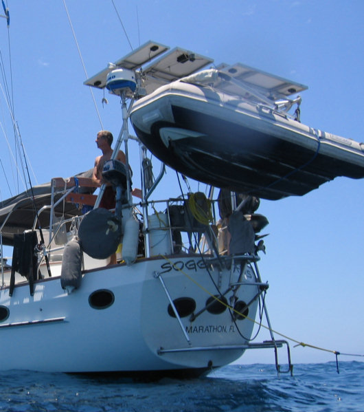
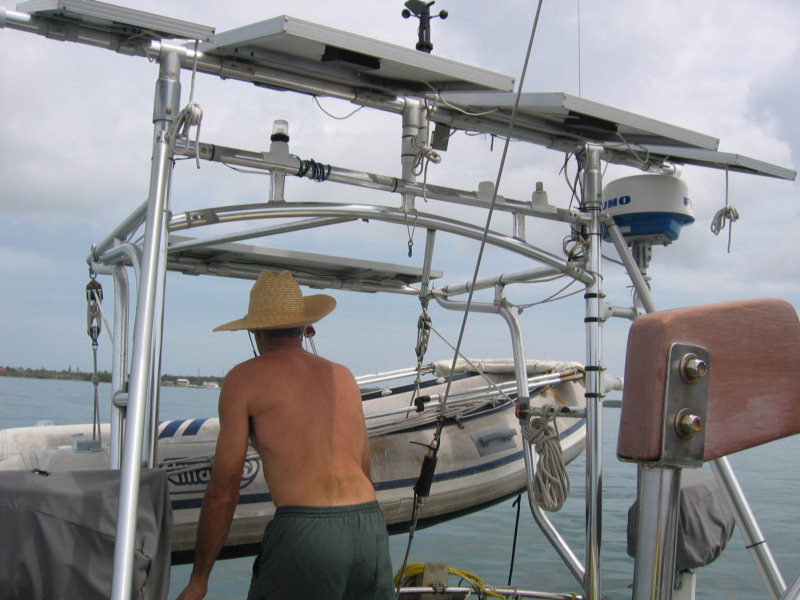
Original: Dave designed and had fabricated this aluminum goal post arch upon which to mount solar panels, radar, wind instruments, anchor and stern navigation lights and dinghy davits.
Originally the 2" main support posts port and starboard extended above the solar panels and held a Windbugger wind generator and the Furuno radar dome. These shaded the solar panels throughout most of the day so that the panel output was severely degraded. This is the case with anything of any size mounted above solar panels so they were remove shortly after returning to the US.
A new aluminum pole was added across the top of the arch and the panels remounted so that they could be rotated fore and aft about 45 degrees each way. Doing so allows the panels to generate approximately 30 percent more amp hours per day.
Another 25 percent was added by wiring the system for 48 volts and upgrading the regulator to the Outbacker solar regulator with the latest MPPT technology. See additional info on the Furuno radar dome mount under the Electronics section.
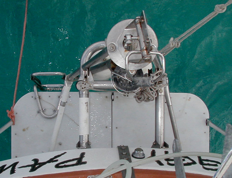
 The
10.5' Alliance RIB dinghy is pushed out gently while being raised and rests
above the wind-vane at stern rail level when fully stowed.
This places it well out of reach of anyone attempting to steal the
motor from a small boat at night. For
open ocean passages it is stowed upside down on the cabin top forward of the
mast for security and so that the Monitor wind vane can be used.
We use triple blocks top and bottom for the falls so that the dingy
is easier to raise and lower. It can easily be strapped in
tightly to prevent chafe when underway.
The
10.5' Alliance RIB dinghy is pushed out gently while being raised and rests
above the wind-vane at stern rail level when fully stowed.
This places it well out of reach of anyone attempting to steal the
motor from a small boat at night. For
open ocean passages it is stowed upside down on the cabin top forward of the
mast for security and so that the Monitor wind vane can be used.
We use triple blocks top and bottom for the falls so that the dingy
is easier to raise and lower. It can easily be strapped in
tightly to prevent chafe when underway.
We carry two outboard motors, a 5 HP and a 15 HP
of the same brand (Nissan/Tohatsu) so that they can use the same fuel tank. One backs up
the other in case of a failure. The 15 provides planing speed for those
long range exploring or diving expeditions while the 5 uses far less
gas for closer dinghy trips while at an anchorage for an extended time.
(top)
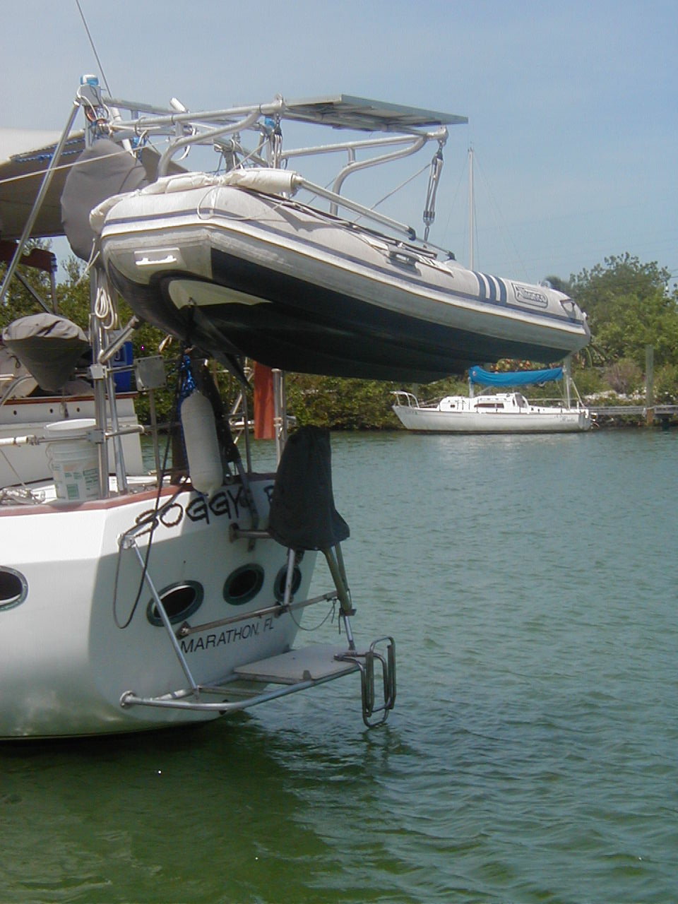
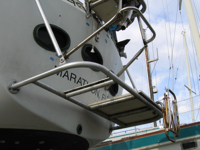
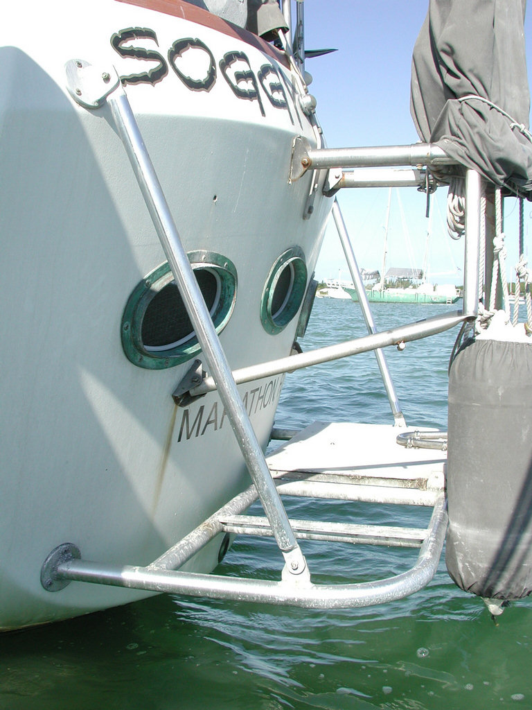
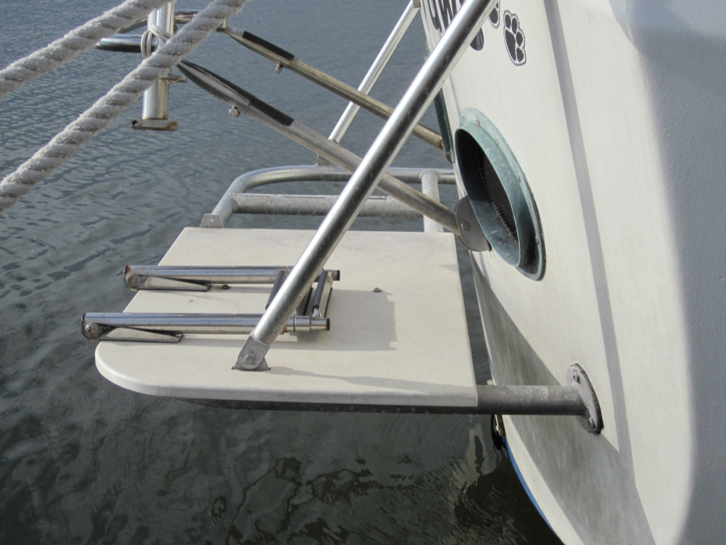
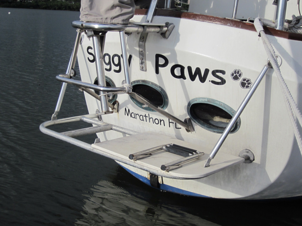
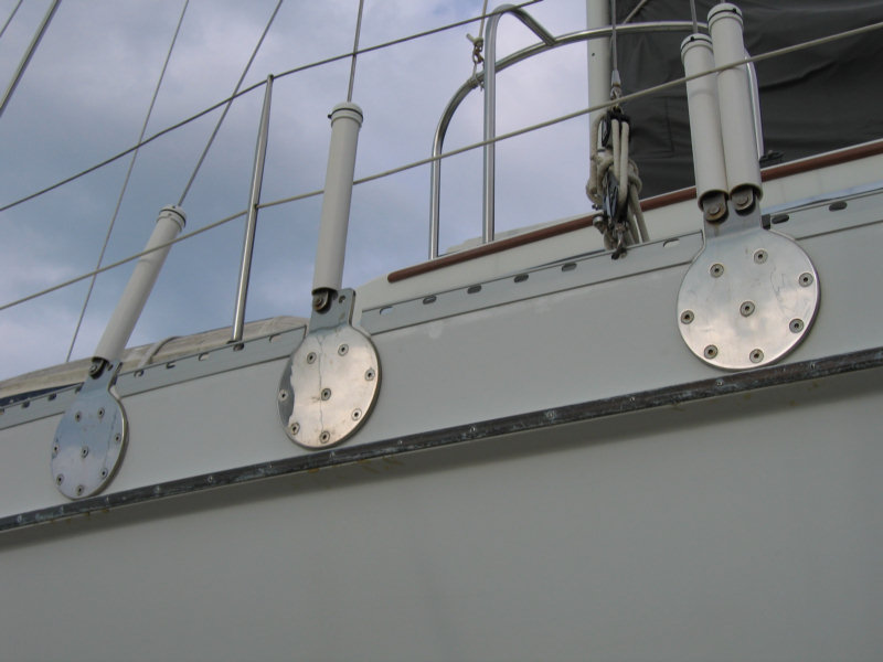
This custom swim
platform is approximately 19" above static waterline, and designed
to handle big seas. The platform decking was originally made
of approximately 55" X 20" of
3/4" white Starboard. We now use only the starboard half as we
rarely go to the port side of the platform. The decking lays on a
permanently mounted 1-1/2" diameter bent and welded aluminum pipe
frame
that can be used by itself for boarding in an emergency. The decking is easily
removed and stowed below by removing 4 bolts. Whenever it is rough enough to stow the dinghy on the
forward deck we remove the platform decking.
The issues for us in designing a our stern swim platform this way were:
-
Allowing room for a Monitor wind vane to be installed

trailing just behind the platform (approx 20" off the stern). -
Ensuring we could lift the dinghy out of the water to a high enough stowed position so that it would be secure from theft and we could use the swim platform while at anchor. When we are using the Monitor for long trips the dinghy is mounted strapped down tight forward of the mast on the cabin top.
-
Allowing partial disassembly by quickly removing the Starboard decking and leaving the frame intact for long passages when we might encounter a gale or worse. This
configuration still allows use of the framework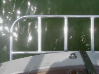 for
recovery
for
recovery
of a man or other objects that fall overboard. -
Providing a platform for swimming, diving, showering, boarding the dinghy, a water level fish gaffing position, and a standing position for the fish cleaning station on the Monitor mounting struts.
Overall we think our $400 expenditure on our swim platform was one of the best projects we've done to Soggy Paws.
Construction and Mounting Details
-
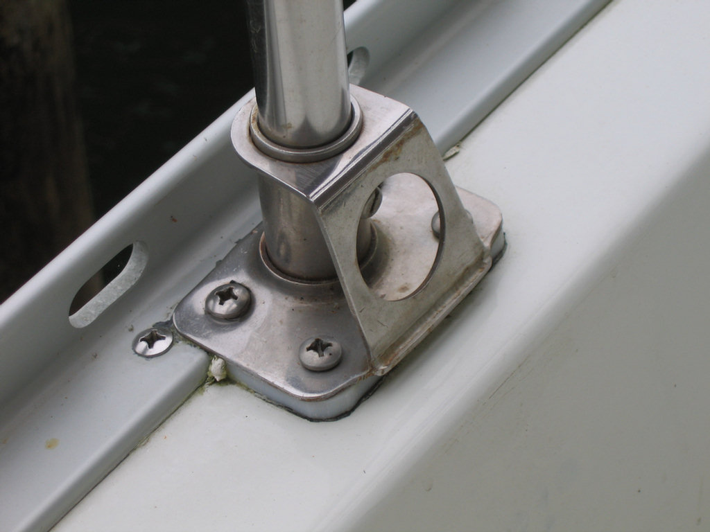
Frame dimensions: 60" wide outside to outside, 21" deep outside pipe to inside pipe, with legs that extend from the inside pipe about 6" to mount to the back of the boat.
Pipe is 1.5" ID anodized aluminum pipe -
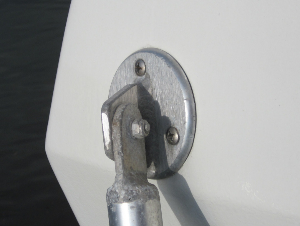
Circular pads to attach the frame to the back of the boat are standard 3-bolt anodized aluminum pads, about 4" in diameter. (see closeup below)
-
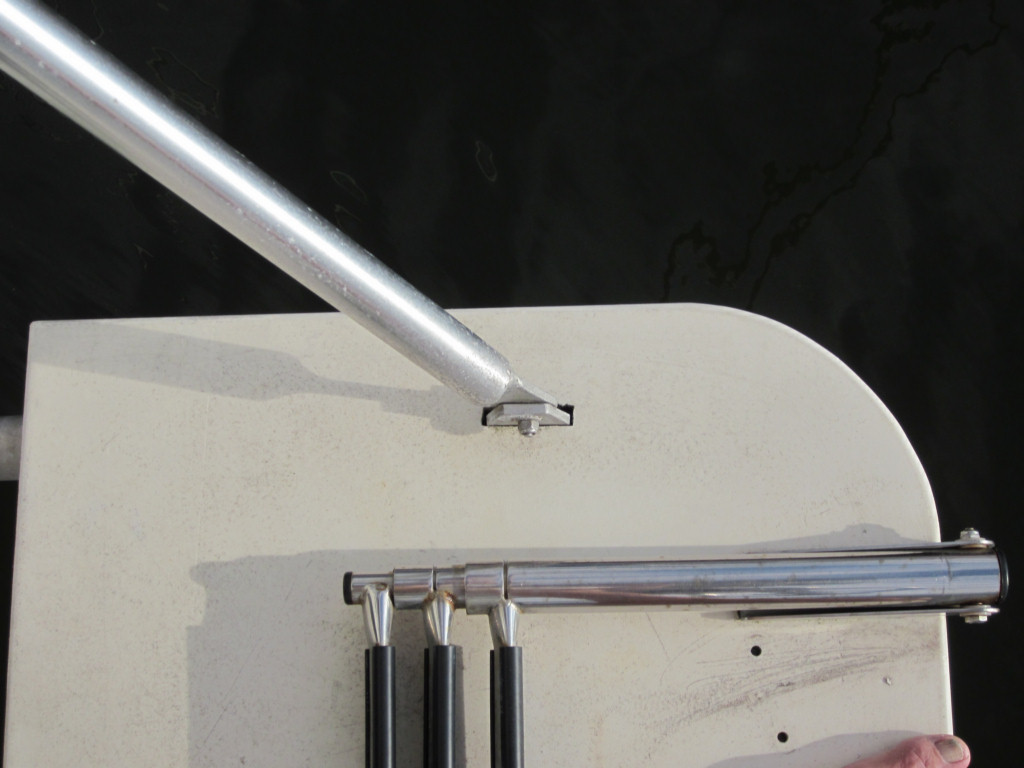
The removable platforms (port and starboard halves) are made out of 3/4 inch white "Starboard"
-
The platforms are fastened with 2 each 1/4 inch SS bolts through a piece of 1 inch wide x 1/4 inch thick aluminium flatbar. The flatbar is welded even with the top edge of the left and right stringers (the 3 bars adding structural stability in the middle of the frame). Only 2 bolts fasten each half of the platform to the frame, in the middle (making it easy to remove when we go to sea), but the platforms each rest on the center bar on one end and the outer frame on the other end. So they are very stable with just 2 bolts to hold them on.
-
The two diagonal supports are made of 1 inch ID anodized aluminum pipe with tabs welded on the end. They bolt to a tab on the top side of the frame and to a tab welded to a circular pad bolted to the back of the boat.
-
Mounting height: 19" from the surface of the water to the top of the Frame.
-
Mounting on a CSY: Years ago we removed the doorskin covering the stern interior of the aft cabin as it was badly wood rotted. So the nuts and fender washers for the lower pads just go through the fiberglass and are exposed on the inside. Someday we will get around to covering that with something. The wood trim is still intact where the upper pad bolts come through the stern of the boat. So the washers and nuts are mounted on this wood trim piece.
-
I recommend installing the lower part of the swim platform first. Then have the welder make the upper support braces such that you can attach them at the lower ends and then fit/rotate the upper pads so that they fit flat to the back of the boat before he welds them to the pipe. My upper pads are attached to a solid insert piece that slides into the end of the pipe. Once the supports are welded, drill the holes and attach the upper pads. They should angle out slightly and fit on the inward angled top of the stern.
-
Future: One add-on I would consider doing is adding a 3/4 inch ID pipe across and under the back of the platform to keep the dinghy from sliding under. This wasn't necessary until we raised the platform 8-9 inches to get rid of slapping in rolly/choppy anchorages. Most modern RIBs have 17" tubes, so with the platform height at 19", they will just go under the platform if you don't have something to prevent it. Mounting a small pipe 3-4" under the aft frame tube should work fine. Any platform height less than about 18" will drag in the water when underway, and slap and bank when in a choppy anchorage (several sleepless nights in 2 years prompted us to raise the platform). So 19" is a good height to prevent this and allow easy access to the platform from the water and dinghy.
|
|
 |
|
 |
 |
 |
| (top) |
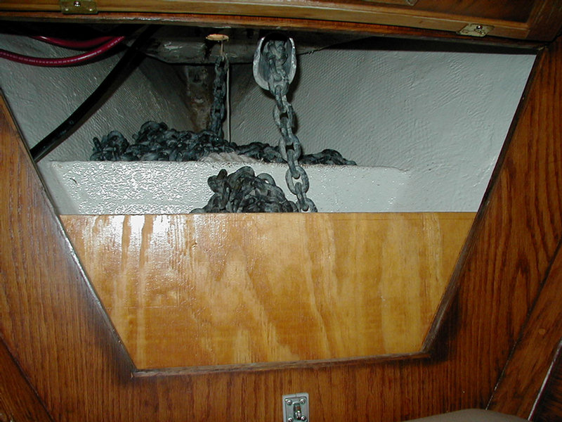
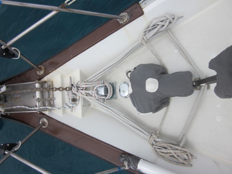
Anchor Locker and Windlass
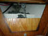
This is the forward chain/rode locker showing the new
athwart ships
divider for chain stowage aft and line/chain stowage forward. This
was a Tom Service (s/v Jean Marie, 44WO) idea slightly modified for our purposes. The new
glassed in 3/4" plywood divider is 14" forward of the aft locker
bulkhead and the top edge is 13" below the overhead. Also shown is
the new 1/2" aft half bulkhead which holds the chain off the locker
door as it piles up. At the top of the locker can be seen the aft
end of the curved aluminum chain pipe used to direct the fall of the
chain 6" aft of the windlass hawsehole. A new line/chain hawsehole
was cut just forward of the Lofrans Tigress windlass base.
(Topica Post 12/28/07) I once had a Simpson Lawrence Sea Tiger 555 manual
windlass but changed it out when the shaft broke for a Lofrans Tigres. We
have been very happy with it for 8 years now. It is a big step in
convenience and safety to move from an all manual windlass to one with both
electric and manual. I have used the manual feature on my Tigres and
although slow it works well. Others have installed the larger, stronger,
heavier and more expensive Lofrans Falcon with equal success. And there are
several other brands that come highly recommended. Get a spare brush set for
which ever windlass you chose.
I installed my Tigres on a custom made fiberglass mounting block that sits
the windlass about 2 inches off the deck. With that height you can still use
reasonable length bolts, get almost 90 degrees turn of the chain around the
chain gypsy and still not have a huge lever arm as you would with a mount
high off the deck. Going up 8 or 9 inches just to get exactly 90% turn on
the gypsy is not what you want to do. I used no caulk but EPDM rubber
gaskets between the deck and mount and mount and windlass. So far no leaks.
While you are mounting the new windlass consider rearranging your anchor
chain locker so that the chain weight is as far aft as possible and the
spare rode is forward. A description of our setup is on the website. Ron
Sheridan, of Memory Rose, has a unique arrangement with the chain and
windlass coming down the starboard side of the boat.
Also while you are at it, pay some attention to your anchor roller tray and
any improvements you might want to make to it, like beefing up the roller
pins, providing rollers where necessary to keep the chain from chafing
against it, and changing to an aluminum grooved roller for your chain. An
easy solution to getting at the nuts under the roller tray (and those for
the forward chain plate) is to cut a rectangular hole in the vertical deck
section just behind the tray large enough so you can get a wrench on them.
Then seal a plate over the hole with screws and an appropriate gasket when
you are finished. Obviously, whatever you do make sure all is absolutely
water tight and as strong as possible with no significant weak links.
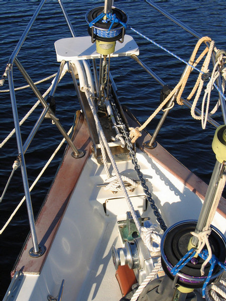
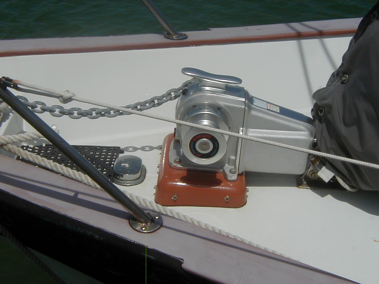 Lofrans Tigres 1200 Watt windlass on custom fiberglass mount |
 Chain locker aft, spare rode forward, the first 100' of chain is led aft through a PVC pipe and stored in the bilge just in front on the mast |
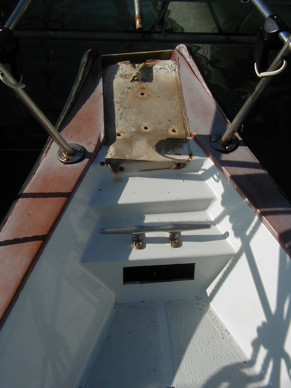 Anchor roller tray removed, access hole open in vertical deck |
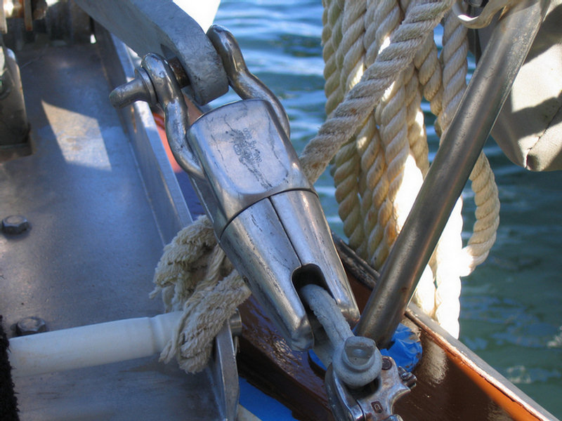 INOX Kong SS swivel, 6000 lb working load exceeds HT chain SWL, shackles match chain 5200 lb SWL |
 Anchor roller tray with 5/8" roller pins and shortened by about 10" |
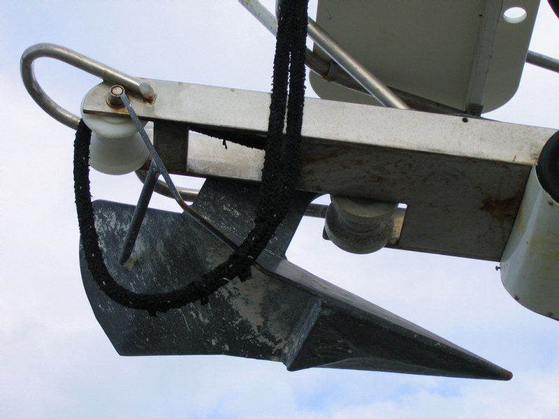
 Bow ground tackle rigged for Hurricane Wilma |
We now carry 300' of 3/8 HT chain (200' in the aft bin and 100'
stretched aft under the V berth to a floor locker just forward of
the mast), and 300' of 3/4" 3
strand nylon line with 45' of 3/8" HT chain in the forward bin.
We also carry considerable additional chain and
line rodes in other lockers mainly under the floor.
The windlass solenoids and remote up/down hand control are mounted
high up on the port side aft bulkhead with the remote coming out the
forward hatch for use on the fore deck. Mounted outside on the stem
9" above the waterline and stoutly backed inside is a new 1/2"
Winchard high strength bow eye used as a no chafe snubber attachment
point.
Note, we continue to have problems with wired remote--the wires fail from flexing and we've had to re-wire it ourselves. We finally bought a very inexpensive wireless remote in late 2012. This works great, with the wired remote as a backup if necessary (top)
I have owned my CSY 44 for 10 years now. The boat came out of charter with a 45 lb CQR, a Fortress 37, two 12' lengths of SS chain and about 200' on 3/4" nylon in two sections. I soon dumped the undersized CQR and replaced it with a Bruce 66. Two years later I replaced the Bruce 66 because of its ability to pick up boulders in its flukes and difficulty setting in grass and soft mud. I started out with a Delta 55 anchor for our trip around the Carribbean and later added a Delta 88. We now have 5 anchors onboard for our circumnavigation: Delta 88, Delta 55, Fortress 55, Fortress 37 and a Danforth 35 HT. I started with 3/8" SL (short link high tensile) chain. Since the chain has a working strength of about 5200 lbs, I use two shackles of the same strength between the chain and anchor: a High Tensile 7/16" (the largest that will fit through the chain standard end link) and a regular 5/8" into the anchor.
If you use BBB 3/8" chain, it's working strength is only 2900 lbs, so lesser shackles could do. If you do have a weak link, it should be at the anchor/chain connection so that if you do break your ground tackle you will only lose the anchor and not the rest. Obviously it should not be much weaker.
We use a Lofrans Tigres windlass strongly bolted through a 2" fiberglas mounting pad to the deck. For snubbers I have an assortment of all 5/8" lengths of 3 strand nylon in lengths of 10-35'. They can be fastened to the boat through closed chocks or over the bow rollers to any of six heavy bow cleats. Another option I like is to attach a snubber to a heavily reinforced stem padeye near the water line.
I don't think that having a swivel
will help those that are having a problem with their anchors dislodging
in changing winds. I think that would be more a problem with the anchor type
vs. the bottom and/or the setting technique.
From the start, I was in the habit of end-for-ending and remarking the chain
about every year and a half when I was at a dock. I had the chain re-galvanized once in 2002 to help extend it's service life. Between late
1998 and 2002 we often anchored for two weeks or more in one place while
cruising in the Caribbean. Since then while doing charters in the Fla Keys I
never anchor more than a night or two in one place. I finally replaced
this anchor chain in 2006, in preparation for our circumnavigation.
I used to have no swivel in the ground tackle and this worked fine, except
that occasionally I would have to back out most of my 200' of chain to
unravel the twists. This was reduced somewhat when I had a chain groove cut
into the aluminum anchor roller on the bow. Even so it took some
considerable attention and time to minimize the twists in the chain as it
came up after anchoring. Then about a year and a half ago I noticed the
chain starting to twist up again while on charter and before I had time to
undo the twists I had a problem.
As the wind picked up one night at anchor I
went forward to let out a little more chain and the twists jammed in the
chain pipe below the windlass. I realized then that if this had been a
really serious situation and I had had to let out more chain or dump it to
save the boat I would have been in trouble. Since the chain was near the end
of it's service life I replaced it a few months later with 300' of new 3/8"
HT ACCO chain at $2.50 a foot. It took us over a half hour to get all the
twists out of the old chain as it came out of the chain locker and up
through the chain pipe. Part of the new chain is now led aft through a large
PVC pipe in order to reduce the weight in the bow.
Many quality swivels and shackles you could buy are only rated for the BBB
chain, and if used with HT chain become a very weak link. That problem,
severe corrosion, improper rigging and lack of mousing were problems with
many of the boats that have reportedly lost their anchors due to problems
with swivels or shackles.
Asian chain, swivels and shackles have a
reputation for flawed construction and are always suspect in my mind.
Typical are those that are not marked with a working load (SWL). Many
swivels used in moorings are always underwater and never inspected until
they corrode through. Take a close look sometime walking down the docks in a
marina at the number of severely corroded, improperly rigged or unmoused
shackles used in ground tackle on seldom cruised boats. The large
professionally engineered and annually inspected mooring field in Boot Key
Harbor does use a large swivel in their design. The design is rated for 50'
boats in a Cat 2 hurricane. It is obviously most important to properly size
and maintain any swivels or shackles used in ground tackle.
I had resigned myself to put up with the chain twist until a very
experienced friend with a similar boat and ground tackle came across what
looked to be a proper swivel. The engineered swivels we bought about a year
ago through West Marine (special order) are made in Italy by a very old
company making nautical fittings. It is very high quality, 316 SS, tested
and patented. It comes in 3 sizes and mine has a working strength of 6600
lbs and a breaking strength of 21000 lbs. On the instruction sheet is
printed "KONG, Bonoiti, since 1830, INOX AISI 316 Swivel Anchor Connector".
Cost was about $130. I still use the same two shackles to make the
connection between chain, swivel and anchor.
Hopefully it will help reduce the twisting of my chain in the future.
2014 Update: In 2013 we sold our Deltas
and bought 2 "new generation" anchors... a 99-lb
Spade and a 65-lb
Mantus. See
Dave's
2013 SSCA Presentation on Modern Anchors and Ground Tackle for all
Dave's research on anchors.
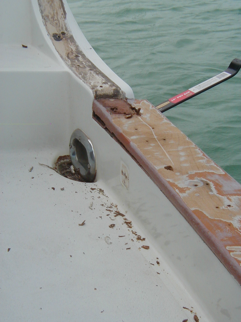
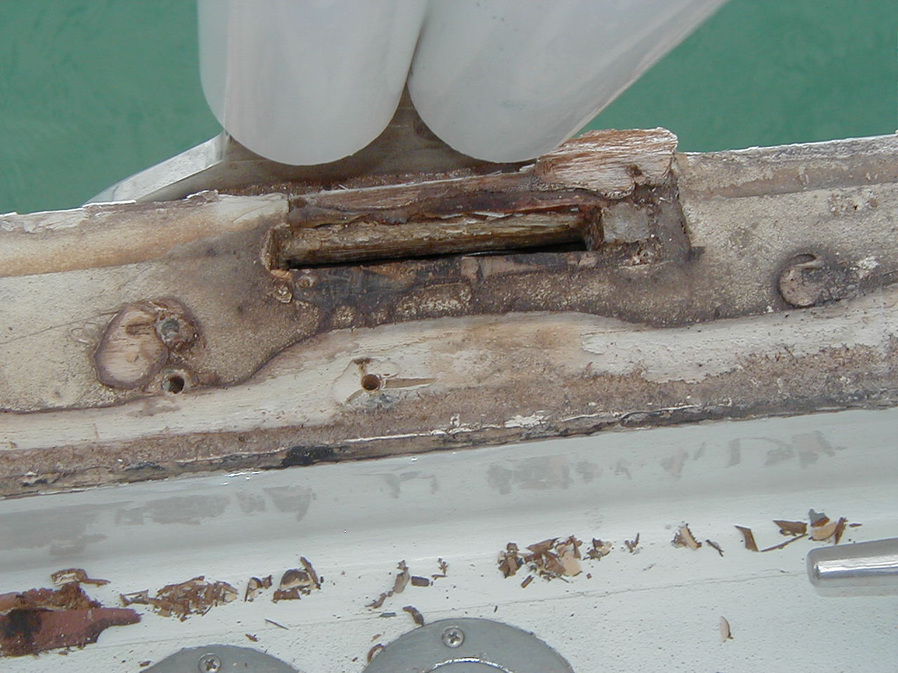
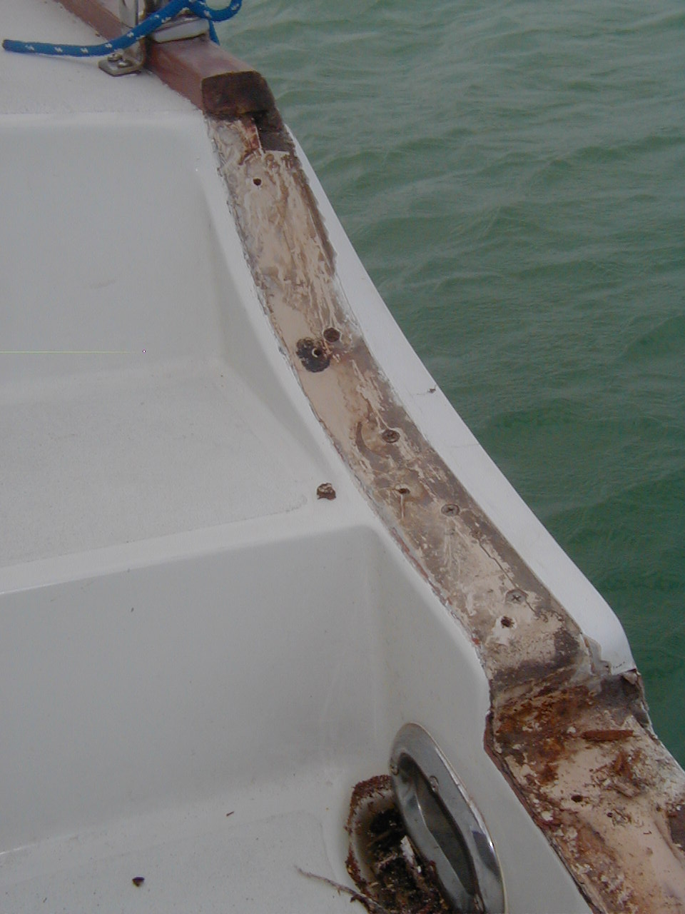
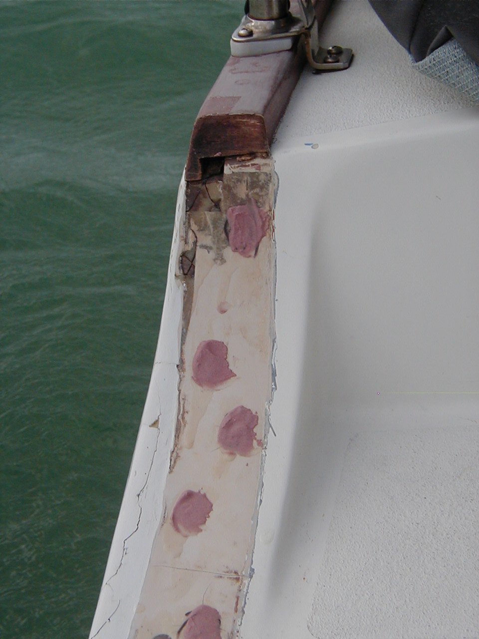
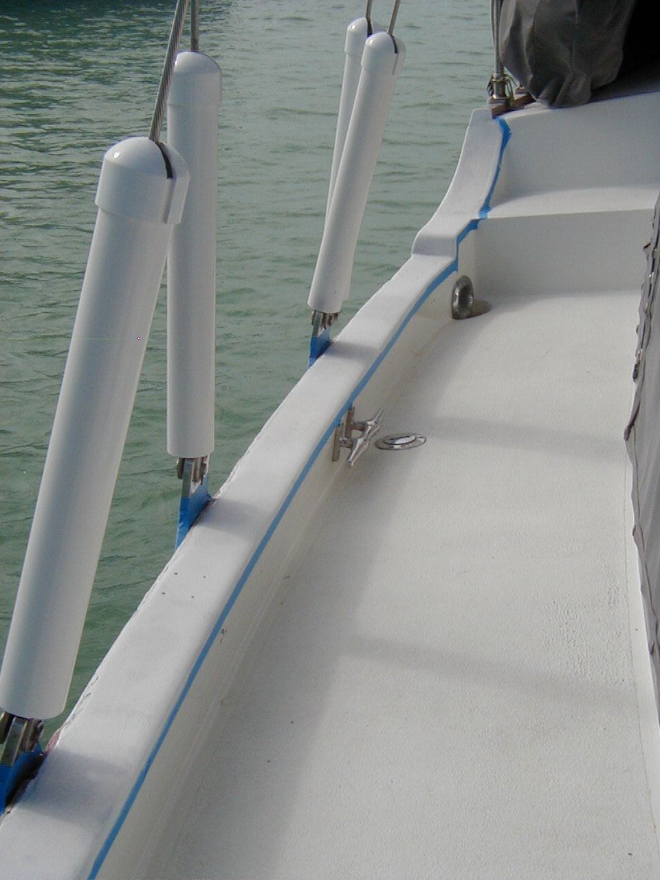
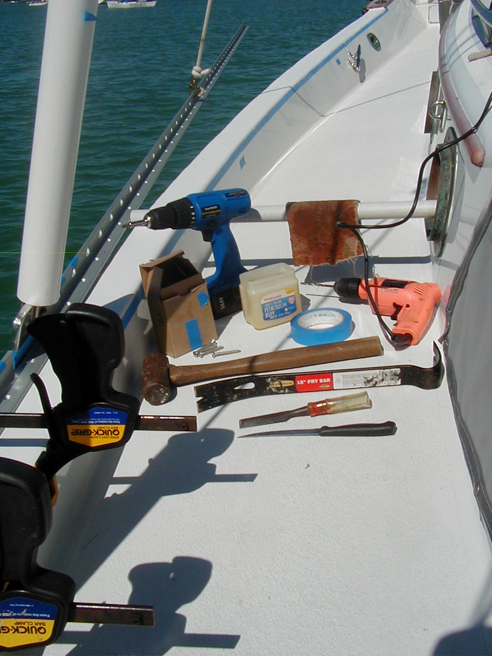
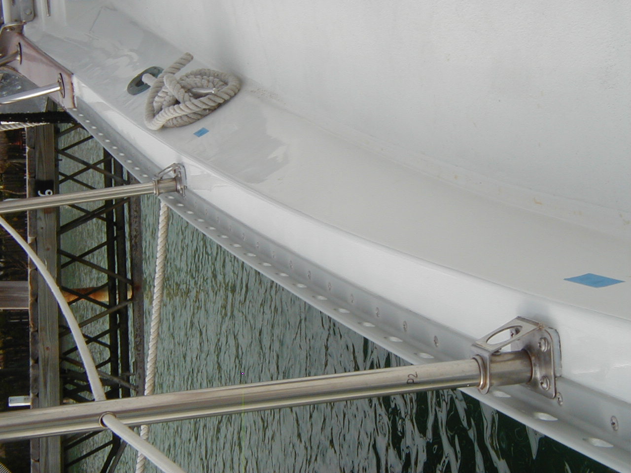
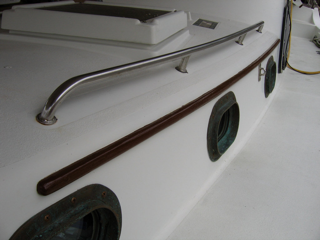
(31 Oct 09 CSYO Post) Hull Rig, Hull to Deck Joint Leaks
Re the hull to deck joint forward: The vertical side of the hull
(topside) comes up and then turns inboard at the caprail. The deck runs
outboard, up to form the bulwark then outboard over the hull layer and just
under the wood caprail. So from top to bottom on top of the bulwark you have
the 1" thick teak caprail, the 1/2" thick deck fiberglass layer and finally
the 1/2" thick topside fiberglass layer.
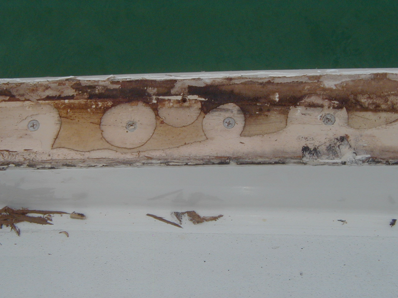
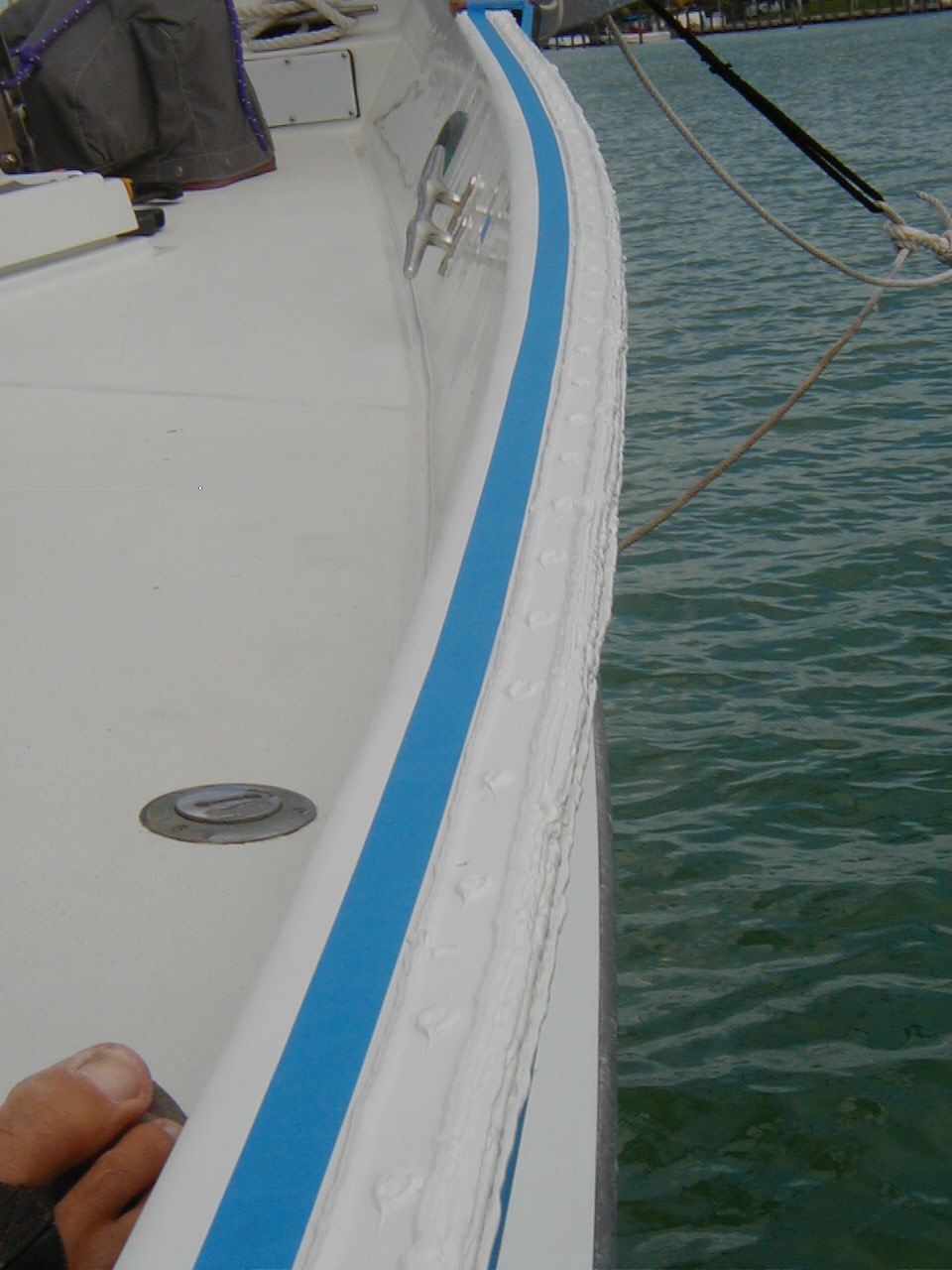
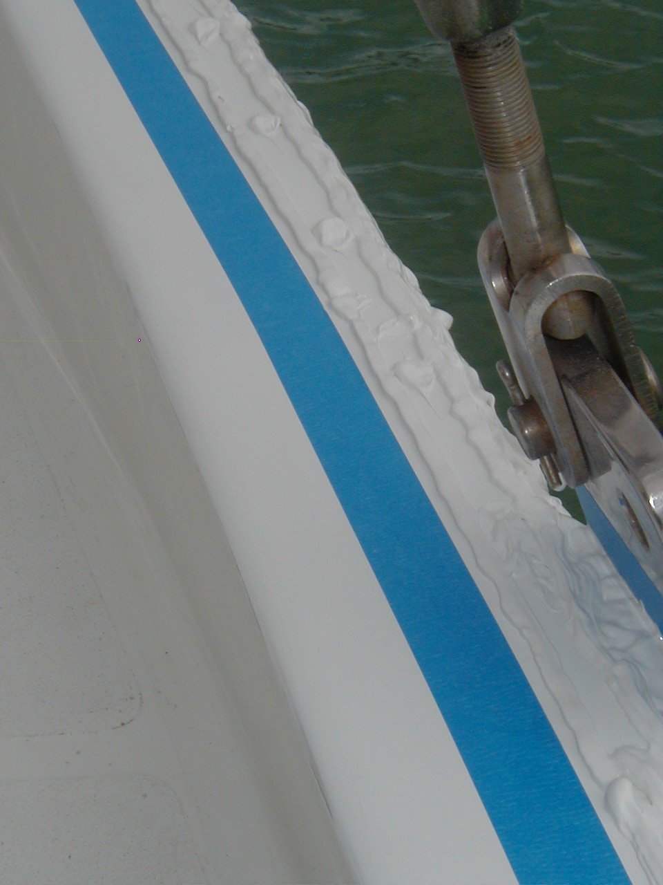
3M 5200 makes the seal and forms the bond between the 3 layers. The joint is
mechanically fastened with alternating 1/4" screws and bolts on 4" centers.
The cause of most leaks is because the sealant is applied in a thin line and
does not make a complete seal between the layers. You probably saw the pics
of this on our website under Deck. Water can get into the joints through an
unpreserved raw teak caprail, screws/bolts with loose bungs, the chainplates
which go through the joint, the outside edge of the joint, loose/poorly
caulked stanchion bases and anything else that may be fastened to the
caprail.
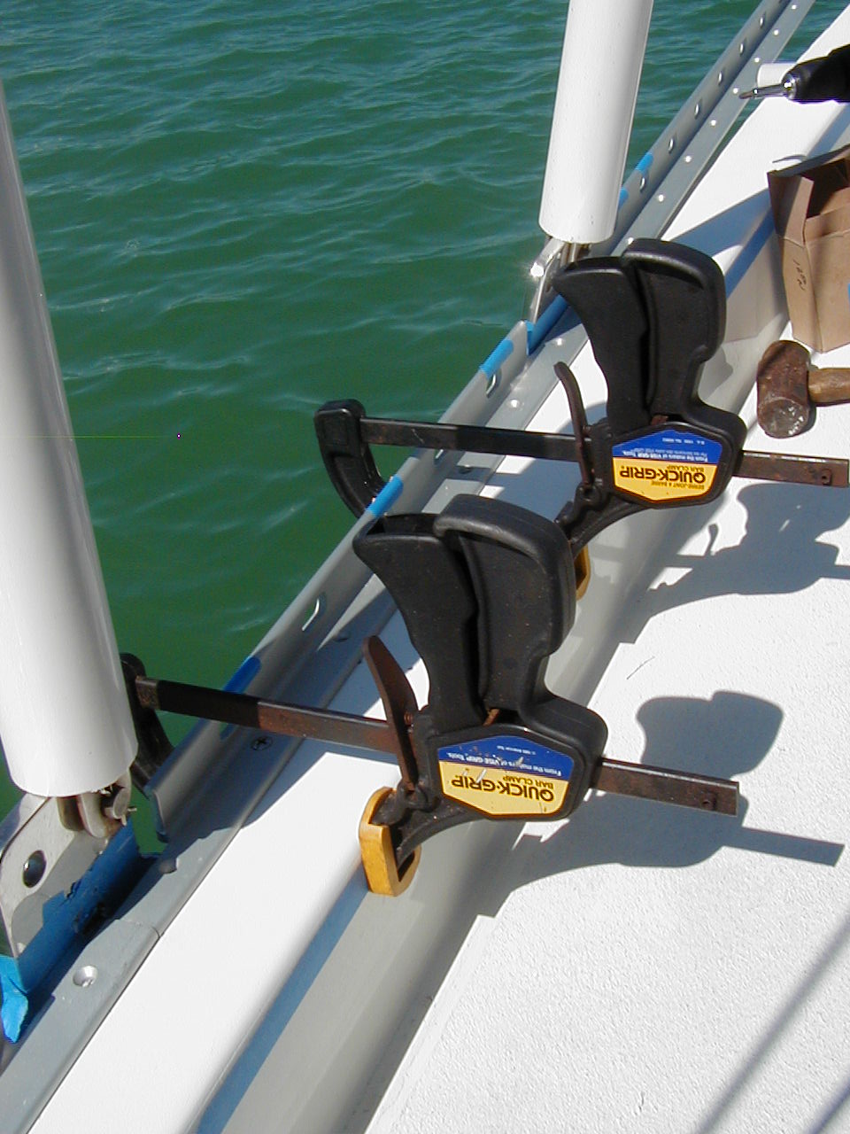
After 8 years of living with the original CSY 44 teak cap rails and their various problems I finally decided to do something about it. I looked carefully at all the replacement options including teak, oak, Douglas fir, various plastic/wood mixes, fiberglass and aluminum edge extrusions. Both Jim Dill of Chilly Pepper and I reached the same conclusion and ordered the only aluminum extrusion in existence that will fit--a heavy duty extrusion built by Taco Metals in Miami. Three 34' sections were enough to do both boats. We both had previously replaced our chain plates, mine external, Jim's internal. We also had each redesigned and replaced our lifeline stanchions. Here for any of you interested in a month's worth of work on your 44 CSY are the steps involved in the process of removing and replacing the cap rails with an aluminum extrusion.
|
|
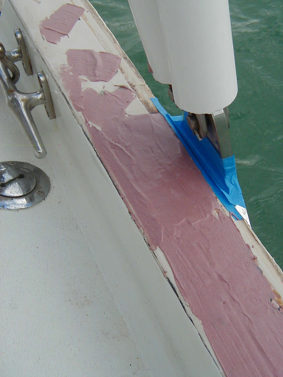
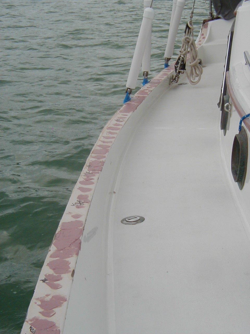
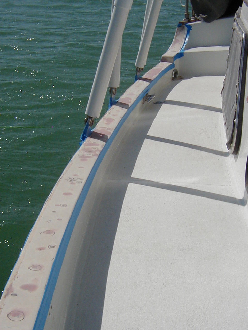
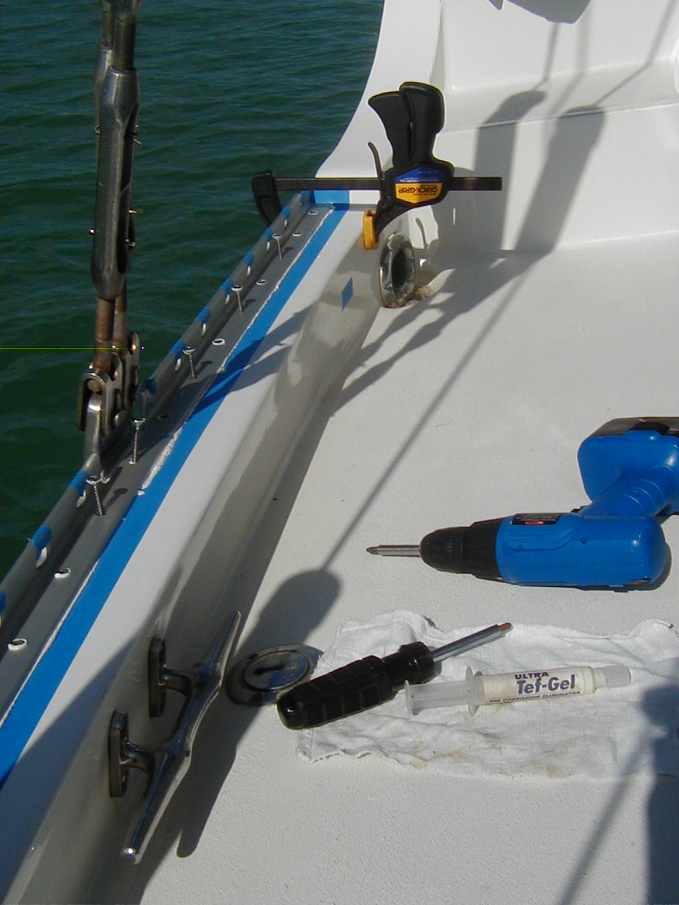
And that's all there is to it! Total cost about one boat unit, $1K. Major benefits include a watertight cap rail, a bullet proof outboard edge, a strong attachment point for such things as roller reefing blocks, fenders, and running rigging and best of all no more varnishing. As painting and fiberglass work are not among my strong suits, many thanks to Ron of Memory Rose for advising/supervising and helping me with this project. Without his help it wouldn't have gotten done. I also had the advantage of watching Jim Dill of Chilly Pepper do his first. (top)
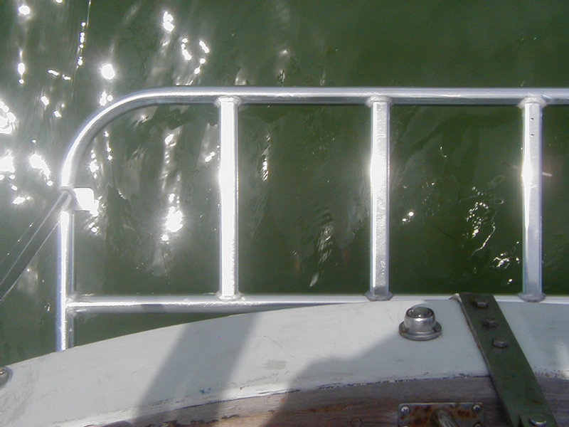
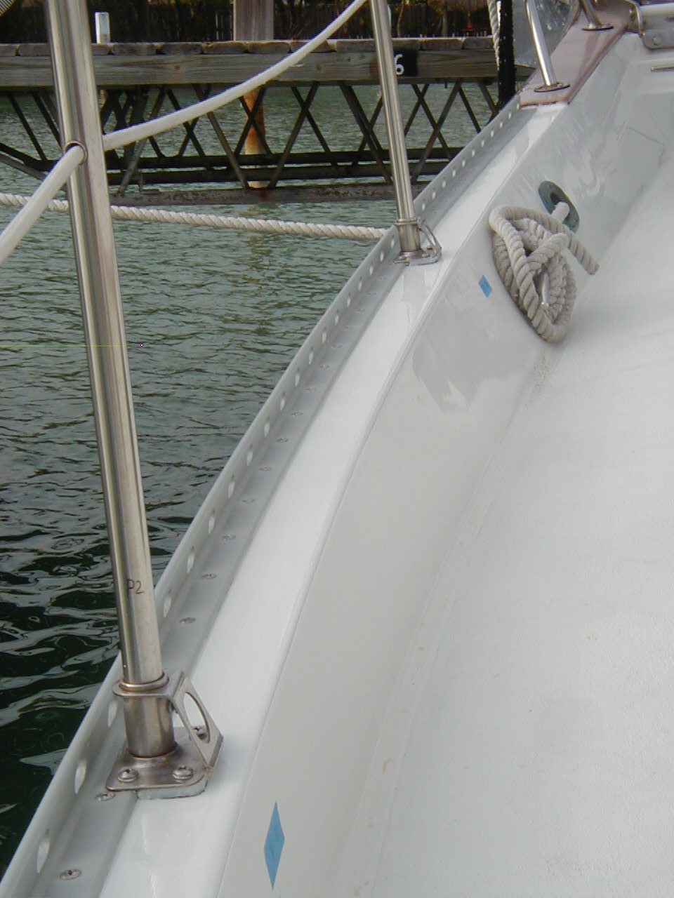
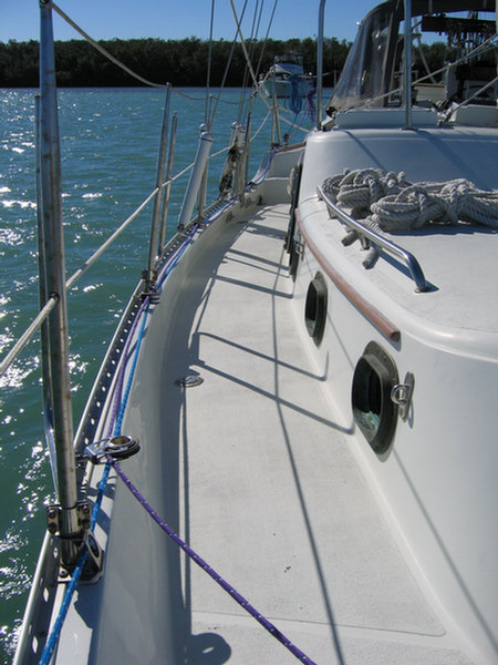
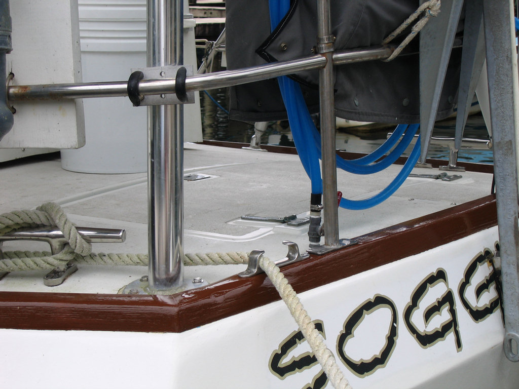
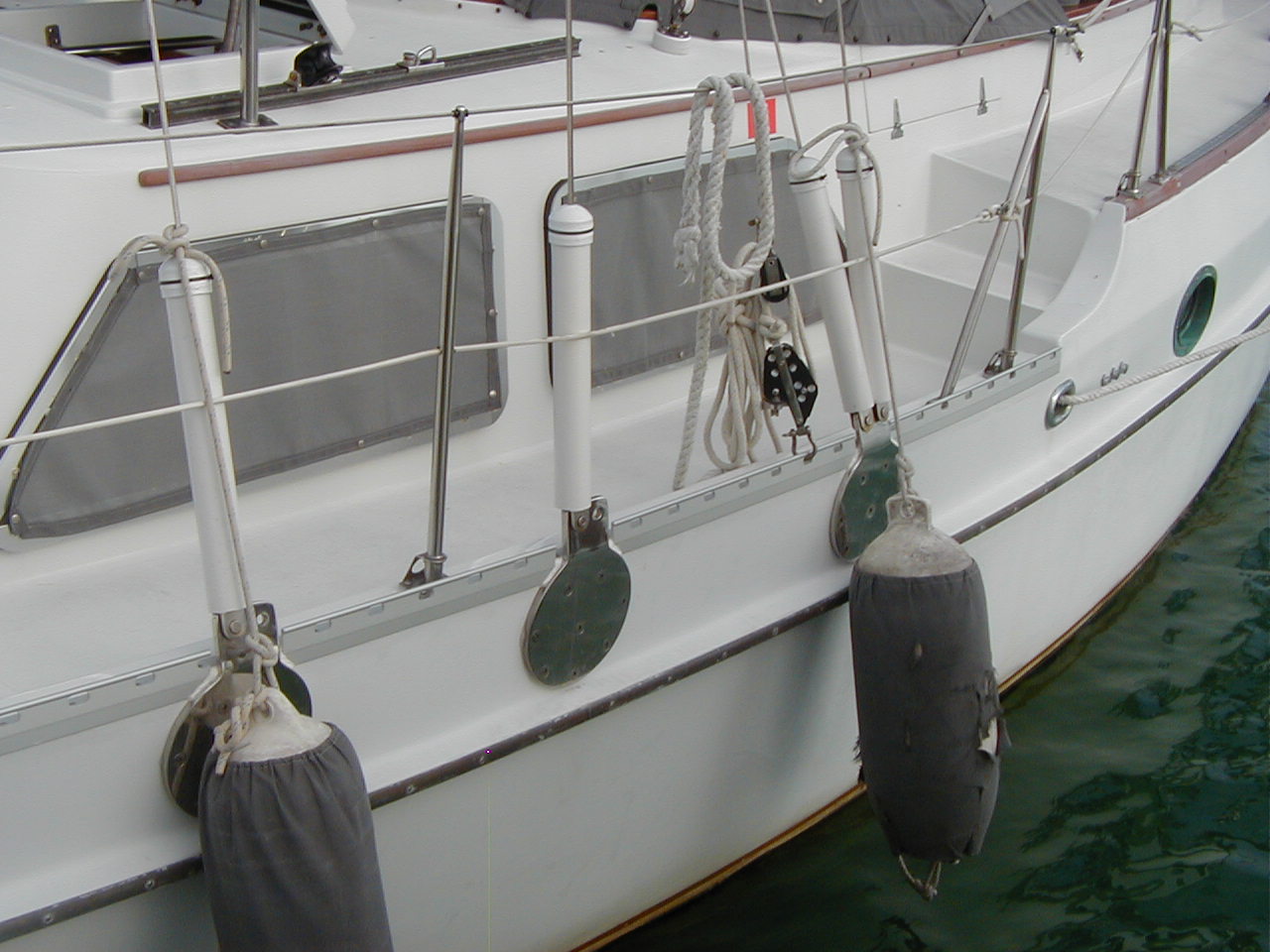
Lifelines
& Stanchions
I have few pics of my aft toe rails and lifeline stanchions. You can see the Schaefer model of two piece
lifeline stanchions in the West Marine catalog under lifeline
stanchions. Mine are Hayn, British I believe, 30" tall and purchased in
Trinidad in 2000 for about $40 per set. They have four holes in the base
plate for 1/4" bolts. When bolted down they are rock solid and have
not leaked a drop. There are many others
available. Try looking them up on the internet.
Here's something else to think about. I read an interesting article not long ago explaining how a 200 lb person thrown against reasonably tight lifelines will produce about 4000 lbs tension at the ends where they connect to the bow and stern rails. If that is true, it is no place for rusty plastic coated 3/16" lifelines, 25 year old 304 SS turnbuckles and jury-rigged railing connections.
I just installed new lifelines
consisting of 316 SS 1/4" 7X19 bare wire with Nicropress fittings and
thimbles on the ends. I'm going to use multiple turns of small spectra
line to tension them, high tensile shackles and beefed up tangs on the
rails in order to try to keep the strength up. Hopefully this will be
enough to keep us lightweights aboard.
 Older design of the Hayn stanchions with a vertical tab welded on |
 Hayn stanchions without vertical tabs bolted through new cap rail |
|
|
|
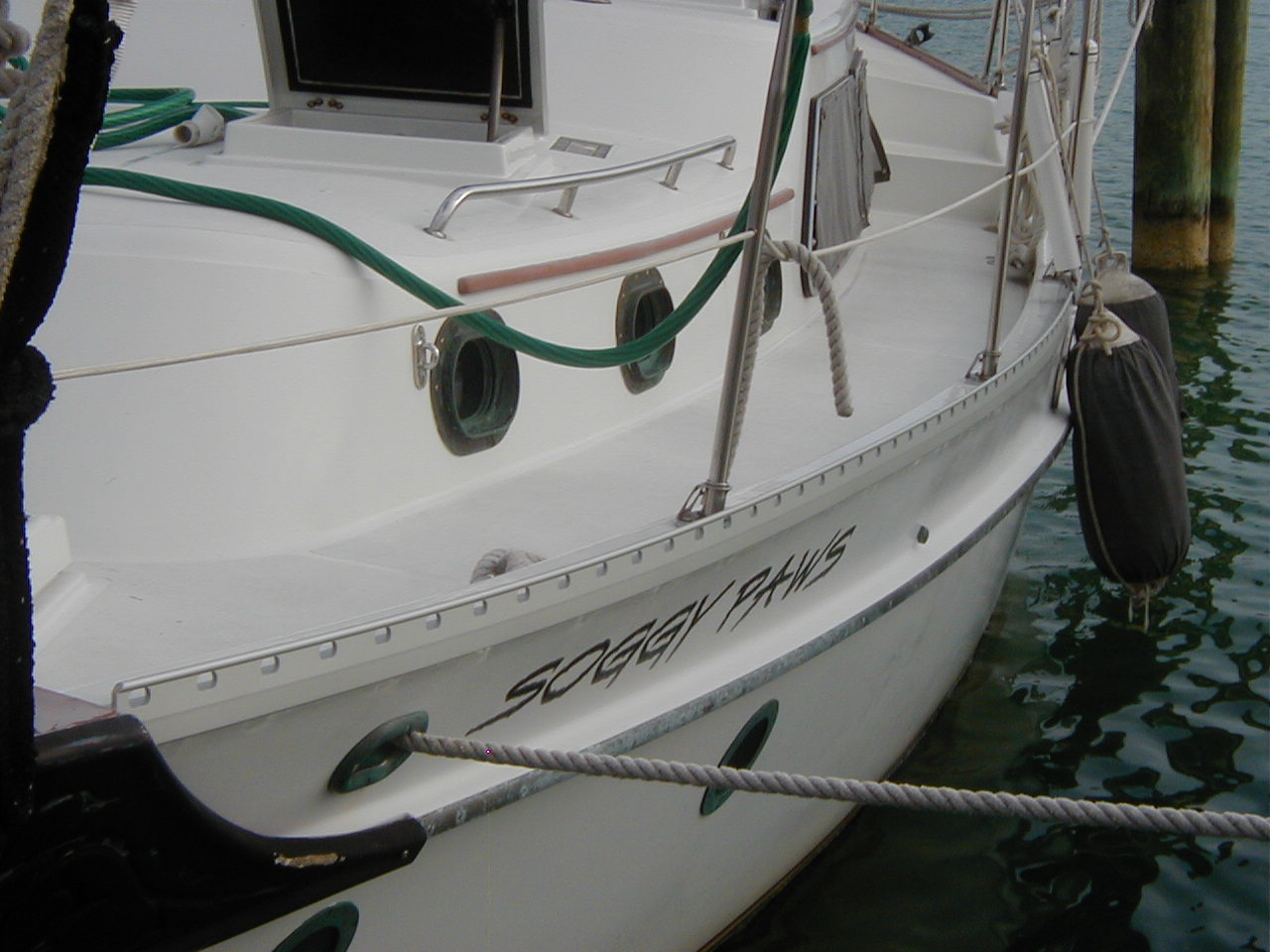
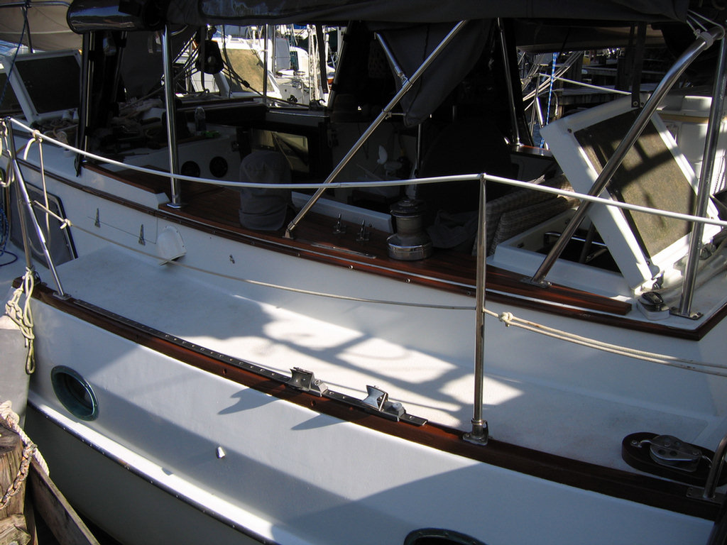
While in Trinidad I used
a cheap locally mixed two part polyurethane by Sikkens on my cap and toe
rails that has been on 5 years, although it is now somewhat sun bleached
on the top. It is still intact but has not been touched in 5 years. Based on
a friend's recommendation, and he knows paint, I will repaint my exterior wood
soon using the Napa product. We don't do varnishes on Soggy Paws,
except on the cockpit teak where we use Cetol touched up every couple of
years. We hate to varnish! (top)
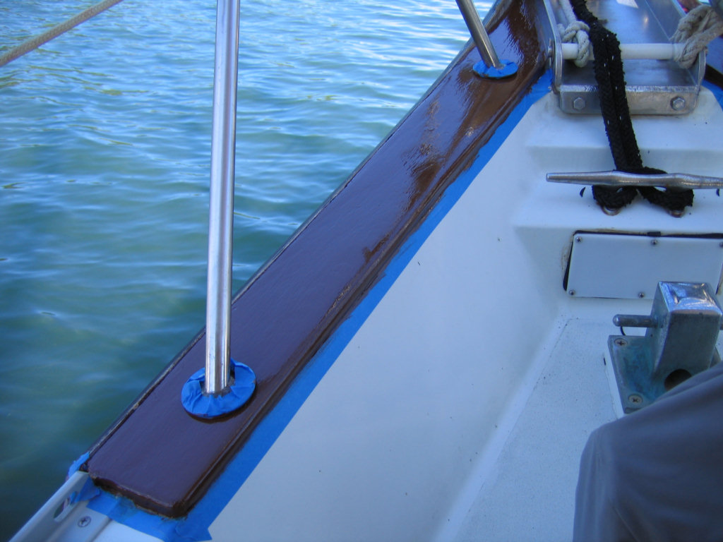
Jan 2008 Update. Just finished having a local painter, Arnulfo Juares, here on the Rio Dulce paint our eyebrows and aft toe rails using a Napa two part MSD urethane enamel we bought in the U.S. We had it custom-mixed at the Napa (auto parts) store to match a color swatch we had. It is a deep brown, just a little more brown than the light teak cockpit combing. While we were at it, we removed the jib sheet lead block tracks to rebed them as they were leaking badly. After a good sanding, Arnulfo cleaned the areas to be painted and touched up any bare wood with two coats of epoxy. Then he applied two coats of the paint one right after the other. Now that it is dry, it is hard as a rock and hopefully will last a long time. It sure looks good!
 Aft toe rail with Trinidad brown paint, 6 years old |
Fwd port cap rail with Trinidad paint |
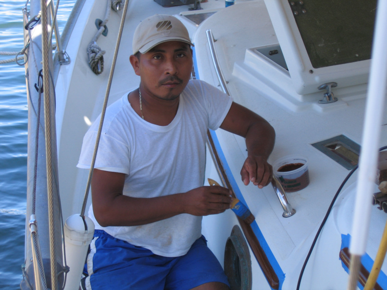 Arnulfo Juares applying first coat of Napa brown MSD paint |
 Fwd port cap rail with two coats of Napa paint just applied |
 Bow cap rails with Napa paint |
 Port eyebrow with Napa paint |
 Port aft toe rail with Napa paint |
 Comparison of port toe rail with Napa brown paint and teak cockpit combing with Cetol |
2014 Update: This paint has held up really well in the harsh tropical Pacific climate we have been traveling through (hot, salty, humid, harsh sun).
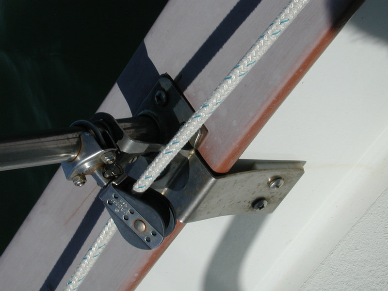
It is easy to rebed the mid ships closed chock. Just remove the two bronze end pieces by removing the 4 self-tapping screws that hold each piece to the bulwark and gently pry them off. Inside is a fiberglass tube that can be removed and then rebedded.
When I did mine several years ago the tubes were actually too long and did not allow the end pieces to seal against the bulwark properly. You may have the same problem. If so just grind the ends to shorten it up so it fits properly. Use plenty of caulk carefully placed when you rebed them. Mine are now chromed and in good and tight. (top)
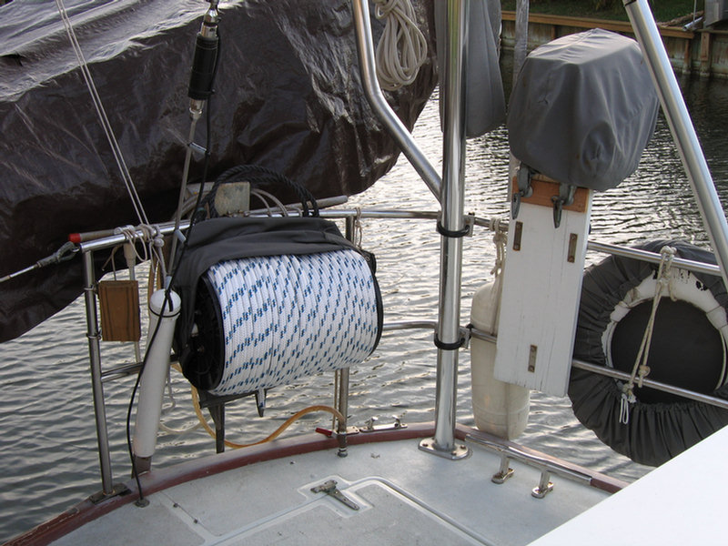
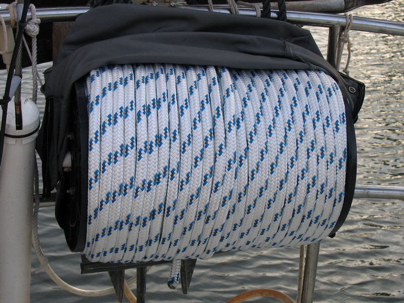
| This line reel is made of
two plastic ends from a West Marine spool of line, a PVC inner tube
about 20" long, some
1/4" allthread and nuts to hold it all together. It holds 500' of 5/8"
polyester double braided line. The line can be used for many things including running out a kedge anchor, towing a drogue, tying a long line to shore and as a messenger for a heavier towing line. The reel mounts ready for action but out of the way on the stern rail. It has a Sunbrella cover to protect it from the sun. |
  |
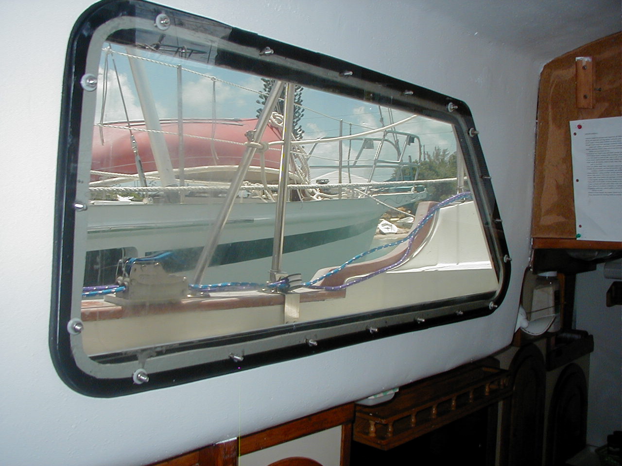
The new main cabin windows were constructed and installed in 2004. The goal was to solve the storm window storage and last minute installation problems by having permanently installed bullet proof windows of sufficient strength to withstand storm wave conditions from the beam. The windows are constructed of 1/2" Polycarbonate/Lexan on the outside and 3/8" on the inside, sandwiching the cabin sides all around with a 2" overlap. They are through bolted using 1/4" SS pan head bolts through the anodized 1/4"X2" aluminum frame, the outer Lexan, the cabin side, the inner Lexan and finally the original inner fiberglass frame. I used straws to isolate the SS bolts from the aluminum frame, surgical tubing to allow for expansion around the bolts as they passed through the Lexan and nylon washers to isolate the bolt heads and nuts from the frames. The outer seal is provided by the use of 2"X1/4" EPDM rubber flat gasket material between the outer Lexan and the cabin side. Finally a piece of Textlene covers each window to provide some degree of shade and privacy. See Dashew's Cruising Encyclopedia for more details on this method of installation. An alternate method used by Tackless Two uses a strong adhesive product called C 10. See their website in the future for more details.
 Finished windows in place with Textlene covers. |
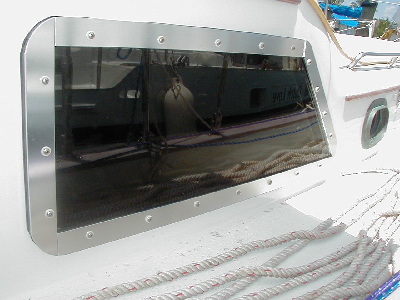 Exterior view showing the frame, bolts and dark tint to the Lexan |
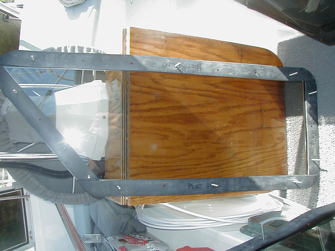 One of the frames from the inside showing the bolt sticking through |
 Inside during installation before the inner frames are installed |
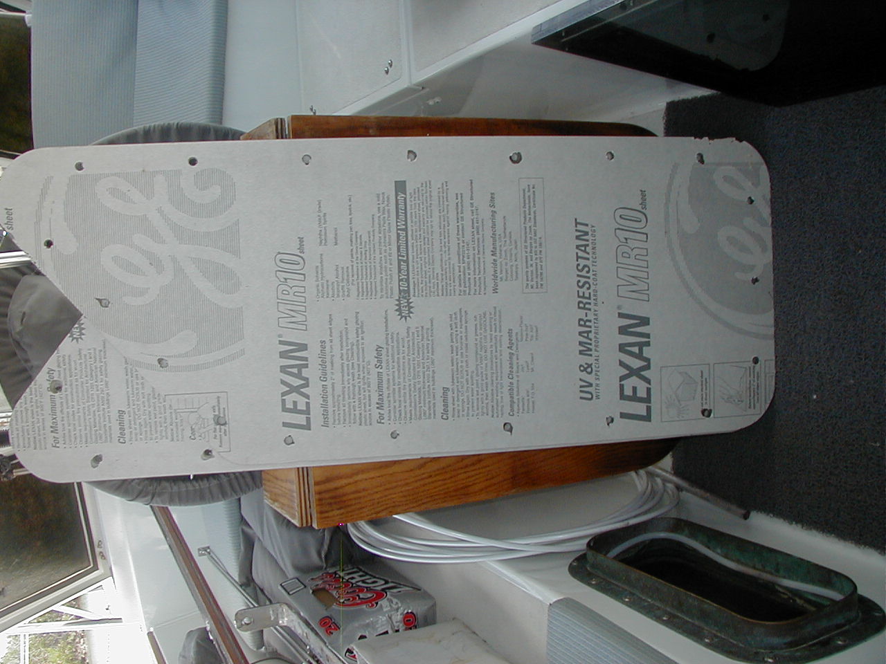 Two of the MR10 pieces cut to size with a saber saw and over sized holes drilled |
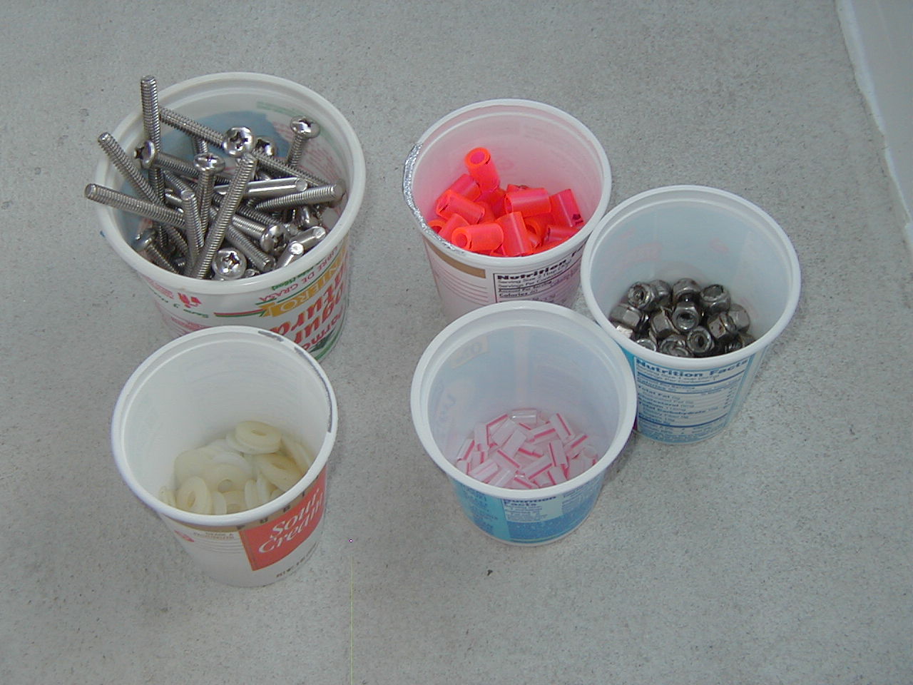 Cups with installation hardware ready to be installed |
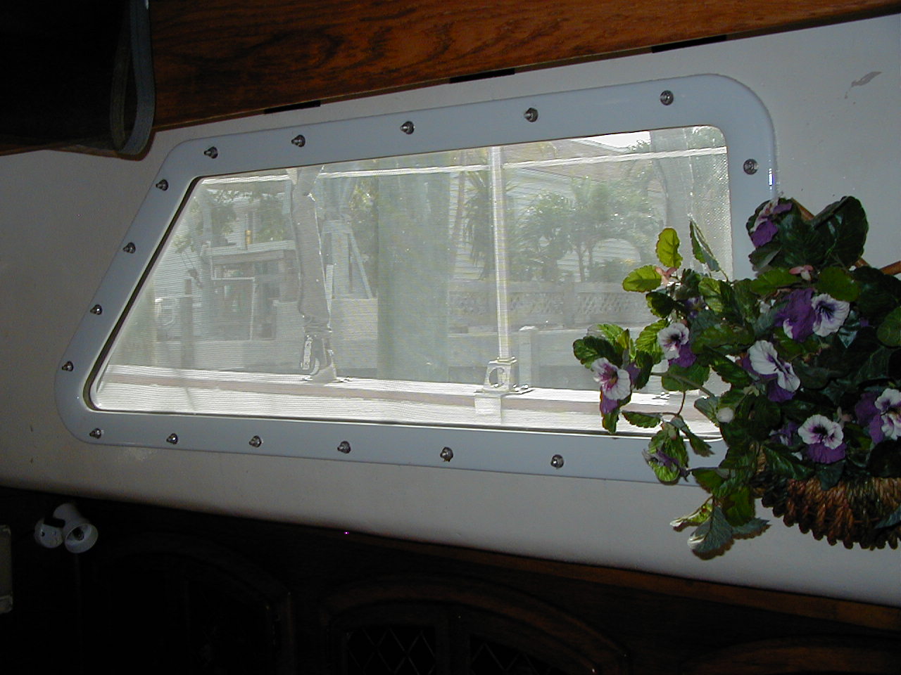 Interior view showing the inside original frame which was reinstalled with nylon washers |
Proper Hook-ups for Mooring Lines
There are lots of
ways to do connect your boat to a mooring. Some ways work better than
others. But if you are using one line run from one side of your boat through
the mooring buoy eye and then back to the other side of your boat you will
certainly chafe through. The problem is the yaw causing the sawing action on
the lines. It is a common mistake and we have seen several boats lost in the
Pacific because of this!.
For reasonable wind/wave conditions you are much better off using a hard eye
on the buoy end of the line and then a large full strength shackle to make
the connection to the buoy line eye. Another way is to use a bridle with two
separate lines and good chafe protection to the boat.
You also have to watch for chafe on the anchor(s) hanging off
your bow, as explained in great detail on this website:
http://www.pbase.com/mainecruising/mooring_prep
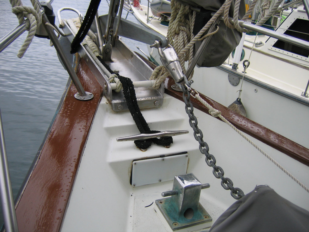
Storm conditions are a real problem because of chafe and heat as the lines
work. So in crowded harbors we use a 7' length of 3/8" G4 chain over our bow
roller to ensure no chafe from the boat. The buoy end is connected using a
7/16" G4 shackle to the chain and then a 5/8" shackle to the buoy. These
sizes give no weak links. On the boat I have the chain connected using the
same size shackles to multiple strong points on the boat's foredeck (we have
six available) using 5/8" polyester/dacron double braid line to minimize
stretch.
Soggy Paws' Storm Mooring Arrangement
- Multiple Attachment Points on the Boat
- Chain over the Bow Roller to Minimize Chafe
- Single Point Release
You have to
minimize chafe in multiple locations so chafe protection is very important.
But tight heavy chafe gear will increase heat/melting of stretchy nylon
lines during heavy surging. So I like G4 chain, full strength shackles and
equal strength low stretch polyester line rigged to multiple strong points
on the bow.
On the foredeck we have the following strong
points:
-the original athwartships mounted cleat just aft of the anchor roller tray
-two cleats on each side of the boat (same size as above), one forward and
one aft of each closed chock, mounted in the inboard sides of bulwarks
-one T shaped heavy bollard mounted on the deck forward of the windlass and
chain/rope pipe
The attachment to the boat from the boat end of the chain is as follows:
-7/16" G4 shackle to the bitter end of the chain
-5/8" SS shackle to the 7/16" shackle
-5 strands of 5/8" polyester/Dacron double braid through the 5/8" shackle
and attached to 4 cleats
-the Dacron is formed into a bight with the closed end of the bight forward
just aft of the anchor roller tray and the open end aft secured on the ends
at the cleats port and starboard. You could use 5 separate lengths of Dacron
with the bitter ends attached to the cleats on both sides of the boat or one
long length. I used one long length of Dacron (a spare jib sheet) wrapping
it around all 4 cleats as I ran it side to side. I repeated this until I had
5 strands of the Dacron through the 5/8" shackle.
-I added a 24" length of fire hose around the Dacron bight running through
the 5/8" shackle to prevent any chance of chafe. It was a tight fit.
The shackles provide full strength of the chain, 5400# working strength or
better, and the Dacron does the same with minimum stretch and no chafe. If
you have to quickly release the boat from the mooring just unscrew the pin
of the 5/8" shackle. just aft of the anchor roller tray. The Dacron stays
aboard and the hardware goes overboard. Our big Delta 88 anchor is tied down
on the foredeck with its chain attached and over its roller so we can still
use it in case we need it.
Inexpensive Wireless Windlass Remote
In November 2012, Dave helped our friend Jack on s/v Kitty Hawk move his boat from a mooring to a dock. Jack had this nifty little windlass remote. We ended up buying not one but two (you always need a spare, and the price was right). We bought ours on eBay for only $40 for two, including shipping!! They are cheaply made, but do the job, and we have a second for backup. (Note, you need a special A23 battery not commonly found, so make sure you get a battery too).
We have since installed it on our windlass--the installation took about 10 minutes to wire the remote's "sender" across the electrical terminals below decks. It works really well, except for a slight lag, which you get used to.
We keep our remote in a ziplock, as it is definitely not waterproof.
Here's a link to purchase on Amazon.com
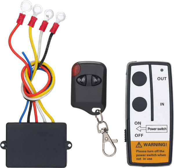
These are made in China, and do not have any safety interlocks on them. Use carefully!!
(top)